


Eclipse Bi-Flame v1.8, Instruction Manual 826, 05/03
5
Function Summary..................................................................
14
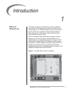
Introduction...........................................................................................
14
Standard Features.................................................................................
14
Combustion Air Flow Check Terminal............................................
14
Main Fuel Valve Proof-of-Closure Terminal ....................................
14
Low Fire Start Terminal ......................................................................
14
High Fire/High Fire Purge Check Terminal.....................................
14
Recycle Mode........................................................................................
15
Pilot Test Mode .....................................................................................
15
Interrupted or Intermittent Pilot .....................................................
15
Spark, Pilot Flame & Main Flame Separation .................................
15
Auxiliary Inputs.....................................................................................
16
History Log ............................................................................................
16
Modulation Contacts...........................................................................
17
Valve Leak Sensing Device .................................................................
18
Remote Display Unit ...........................................................................
19
RS232/RS485 Communication Interfaces ......................................
19
Logic Module Status Lights & Push-buttons ..................................
19
Limits .......................................................................................................
19
Air ............................................................................................................
20
Purge .......................................................................................................
20
Burner On..............................................................................................
20
Fault .........................................................................................................
20
Alarm.......................................................................................................
20
Low Fire..................................................................................................
20
High Fire .................................................................................................
20
Scan..........................................................................................................
20
Enter ........................................................................................................
20
Reset........................................................................................................
20
System Faults .........................................................................................
21
System Lockout Conditions ..............................................................
21
System Installation ..................................................................
22
Introduction...........................................................................................
22
Interlocks and Limit Switch Input ....................................................
22
Combustion Air Switch Input............................................................
22
Ignition Wiring.......................................................................................
23
Communication Wiring ......................................................................
23
Power Supply.........................................................................................
23
Low Fire Input.......................................................................................
23
Main Valve Proof-of-Closure..............................................................
23
High Fire Input ......................................................................................
23
Auxiliary Inputs.....................................................................................
23
Remote Reset .......................................................................................
23
Remote Display ....................................................................................
24
Terminal Strips Identification & Location (Figure 6.1) ................
25
Wiring Diagram & Connections–Main Chassis (Figure 6.2) ........
26
5
6