


Eclipse Bi-Flame v1.8, Instruction Manual 826, 05/03
11
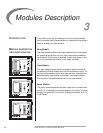
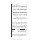
Sensor Module
The sensor module is the flame sensing module of the Bi-Flame. It is
mounted in the furthest right position of the mother board.
On the front of the sensor module are two “Flame On” LED’s, which
illuminate when a flame is detected at the corresponding burner.
Directly below the “Flame ON” LED are “Flame Fail” LED’s, which
energize to show the first burner to lose its signal.
The sensor module incorporates test point connection jacks in the
front of the unit. Using these, the flame signal strength of each burner
can be measured using a 0-15 VDC, one megohm/volt meter as
explained and shown in “Flame Signal Strength” on page 30.
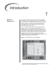
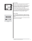
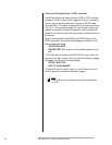
Remote Display
The remote display provides alphanumeric messages which indicate
burner status as well as annunciate lockout condition in the Bi-Flame
system. It also provides remote reset, a keypad and history logging
capability.
A cable connects the remote display to the motherboard; this cable is
available in six and 10 feet lengths.
Sensor Module Location
Remote Display