


Eclipse Bi-Flame v1.8, Instruction Manual 826, 05/03
10
In this section, you will find descriptions of the various modules
which comprise the Bi-Flame dual burner flame monitoring system,
whether standard or optional items.
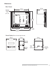
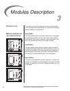
Relay Module
The relay module contains the output relays which provide power
for operating the ignition coil, pilot valve, main valve, combustion
fan and alarm. This module is mounted in the first position on the
left of the motherboard closest to the output terminals.
Logic Module
The logic module houses the microcomputer which provides all
the sequential logic and safety start-up and shutdown circuitry. On
the front of this module is the reset, scan and enter push-buttons,
and status lights. This module is mounted in the second position
from the left of the motherboard next to the relay module.
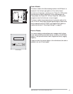
Power Module
The power module supplies the power required for the electronic
circuitry. It is mounted in the motherboard to the right of the logic
module. The green LED on the front indicates that power is on to
the Bi-Flame.
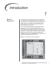
INTRODUCTION
MODULE DESCRIPTION
AND
IDENTIFICATION
Modules Description
3
Relay Module Location
Logic Module Location
Power Module Location