


Eclipse Bi-Flame v1.8, Instruction Manual 826, 05/03
26
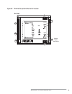
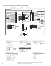
Figure 6.2
Wiring Diagram & Connections–Main Chassis
On/Off
Alarm
Fan Motor
Interlocks & Limits
Air Flow
120 VAC
POVC
15 A. Fuse
6
7
8
9
10
1
2
3
5
4
Low Fire
High Fire
6
7
8
1
2
3
5
4
MS
Aux. Input #4
1
Aux. Input #3
1
Aux. Input #2
1
Aux. Input #1
1
Leak Detect
Neutral
Main
Leak Detect
Pilot
Ignition
1
2
3
4
Flame Rod
Shield
Blue
5600-90A
or 5600-91
U.V. Scanner
Yellow
Main Gas Valve
Block Valve
Pilot Gas Valve
Neutral
J1
Terminals
J2
Terminals
J4
Terminals
2
J5
Terminals
2
Burner #1
1
2
3
4
Flame Rod
Shield
Yellow
Blue
Burner #2
6
5
4
3
1
2
RS 232
Rx
Tx
Remote
Reset
Pushbutton
(if required)
VDK/VLSD
J7
Terminals
When not used, must be tied into 120 VAC.
1
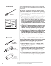
Using both sensors isn’t mandatory; you may use a flame rod, or a UV scanner, or both.
2
J1 (Input) Terminals
1 – Limits Input
2 – Air Switch Input
3 – POVC Switch Input
4 – Low Fire Switch Input
5 – High Fire Switch Input
6 – VDK/VLDS Input
7 – Aux. #1
1
8 – Aux. #2
1
9 – Aux. #3
1
10 – Aux. #4
1
J7 (Interface) Terminals
Auxiliary
Inputs
1 – Flame Rod
2 – Ground (Yellow)
3 – U.V. (Blue)
4 – Shield Connection
1 – U.V. (Blue)
2 – Ground (Yellow)
3 – Flame Rod
4 – Shield Connection
J2 (Output) Terminals
1 – Neutral
2 – 120 VAC
3 – Fan
4 – Main Gas Valve
5 – Pilot Gas Valve
6 – Ignition Transformer
7 – VDK/VLSD
8 – Alarm
Bi-Flame
Power Inputs
Outputs
J3 (Modulation) Terminals
1 – Common
2 – Auto
3 – Hi Fire
4 – Low Fire
Modulation
Motor
Connections
for High Fire &
Low Fire Start
J4 (Sensors/Burners 1 & 3) Terminals
2
Burner #1
J5 (Sensors/Burners 2 & 4) Terminals
2
Burner #2
6 – RS 232/RS 485 Interface
5 – RS 232/RS 485 Interface
4 – Reset
3 – Scan
2 – Enter
1 – Ground
5600-90A
or 5600-91
U.V. Scanner
GND (Return)
D
C
A
B
Signal (UV)
Neutral
120 VAC
5602-91
U.V.
Self-Check
Scanner
VDK/VLSD
Customer Supplied (if used)
1
2
3
4
Common
Auto
High Fire
Low Fire
J3
Terminals
P1-1
P1-2
P1-4
+
-
ACT004
Temperature
Controller
4 to 20 mA
Ignition Coil
Ignition Coil