


Eclipse Bi-Flame v1.8, Instruction Manual 826, 05/03
12
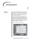
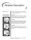
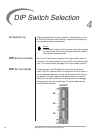
INTRODUCTION This section details the location, selection and description of the
Bi-Flame DIP switches, which allow for sequence and timing func-
tions as well as system configuration.
Caution:
To avoid electric shock, shut off the power supply when installing
any control device. Flame monitoring systems must be installed
by a qualified, licensed technician.
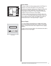
All of the DIP switches are located in the logic module, which is
mounted in the second position from the left of the motherboard
next to the relay module (see page 10 for logic module location).
To gain access to the DIP switches, remove the circuit board
cover. To do this, remove the four screws which hold the cover to
the motherboard. Remove the cover by lifting up and off of the cir-
cuit boards. The logic module is the second board from the left.
Gently pull the logic module with a rocking motion to disengage
the terminal pins at the module base. The photo below shows
the DIP switch locations.
DIP SWITCH LOCATION
DIP SWITCH ACCESS
DIP Switch Selection
4
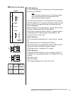
ON/OFF
S6
S4
S2