


Eclipse Bi-Flame v1.8, Instruction Manual 826, 05/03
28
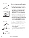
Flame rods should be used only on gas burners. They accumulate
soot on oil burners, causing nuisance shutdowns and unsafe operat-
ing conditions.
See the burner manufacturer’s literature for flame rod mounting
location. When installing flame rods, please consider the following:
1) Keep the flame rod as short as possible and at least 13 mm (1/2")
away from any refractory.
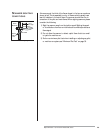
2) Position the rod into the side of both the pilot and main flames,
preferably at a descending angle to minimize drooping of the
flame rod against burner parts. Flame rod position must ad-
equately detect the pilot flame at all burner draft conditions. Ex-
tend the rod 13 mm (1/2") into nonluminous flames, such as blue
flames from burning an air/gas mixture. For partially luminous
flames, such as atmospheric air/gas mixtures, place the rod at the
edge of the flame.
3) Provide a burner/flame grounding area that is at least four times
greater than the flame rod area contacting the flame. The flame
rod/burner ground ratio and position of the rod in the flame
may need adjustment to yield maximum flame signal strength.
4) Ignition interference from the spark plug may increase or decrease
the flame signal strength. Reversing the ignition transformer pri-
mary leads may reverse this effect. Reducing the spark gap or add-
ing grounding area between the flame rod and spark plug may
eliminate the interference.
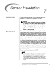
Use only Eclipse model 5600-90A, 5600-91, 5602-91or 5600-91N4
scanners. Consult the burner manufacturer’s instructions for mounting
location. When installing scanners, please consider the following:
1) Position the scanner within 457 mm (18") of the flame.
2) Bushing threads are 1/2 inch F.N.P.T. for scanner models
5600-90A, 5600-91 and 5600-91N4; model 5602-91 has 1
inch F.N.P.T. bushing threads.
3) The ambient temperature limits of each scanner varies, (see speci-
fications). For higher temperatures, use Eclipse heat insulator
49099 or the Heat Block Seal, Model 23HBS, that has a purge fit-
ting.
4) An optional magnifying lens (Eclipse #49600-98) may also be used
to increase the flame signal strength in difficult sighting situations.
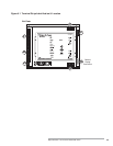
Flame Rod
U.V. Scanner
(Model 5600-91)
90° U.V.
Scanner
(Model 5600-90A)
Self-Check
U.V. Scanner
(Model 5602-91)
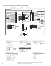
FLAME RODS
SCANNERS
WRONG
Rod Detects
Weak Pilot
PILOT
CORRECT
Rod Detects
Only Strong
Pilot Flame
Flame Rod Position