


Eclipse Bi-Flame v1.8, Instruction Manual 826, 05/03
19
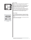
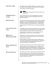
Remote Display Unit
The remote display with keypad allows remote reset and activation
of the history log option. It is panel mountable and features a back-
lit liquid crystal display in a 1/4 DIN housing. It connects to the Bi-
Flame by a six or ten foot cable. The display incorporates the fol-
lowing features:
1) Provides status messages for the Bi-Flame sequence. (See Sec-
tion 10)
2) Indicates lockout conditions when they occur, as well as the
amount of time into the sequence when the lockout occurred
and the amount of time elapsed from lockout.
3) Provides continuous monitoring of each burner’s flame signal
strength during main burner operation. (Pressing ENTER once
will lock on a particular burner’s status; pressing ENTER a sec-
ond time will resume scrolling).
4) Incorporates a remote reset key.
5) Provides the interface required for the History Log.
6) Incorporates keys for pilot test mode.
RS232 Communication Interfaces (RS485 optional)
Terminals 1, 5, and 6 on Bi-Flame terminal strip J7 provide a serial
ASCII output communication interface for remotely monitoring the
system sequence and status using a terminal or a modem; refer to
Section 10 for the types of messages sent by the Bi-Flame.
The communications protocol is 8 bit, no parity, 1 stop bit and1200
baud. This feature is provided standard as a RS232 interface.The RS485
interface is optional.
Sending a carriage return (<CR> = ASCII Hex 0D) from the terminal
causes the Bi-Flame to retransmit the last message. Sending a CTRL-
E (<ENQ> = ASCII Hex 05) accesses the optional history log.
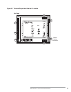
The logic module provides all the sequential logic, and safety start-
up and shutdown circuitry. On the front of the module is the reset,
scan and enter push-buttons, and status lights. This section de-
scribes the their respective functions.
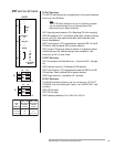
Limits
This LED illuminates when the operation limits are made. These limits
are wired in series to terminal J1-1. This input becomes energized to
begin the burner sequence. When in the test mode, this LED flashes
(see “Pilot Test Mode” on page 15).
L
OGIC
M
ODULE
S
TATUS
L
IGHTS
& P
USH
-
BUTTONS