


Eclipse Bi-Flame v1.8, Instruction Manual 826, 05/03
27
This section describes the proper wiring, installation and sighting con-
siderations for all sensors that can be used with a Bi-Flame.
Warning
Incorrect sensor installation may cause the sensor
to generate a false flame signal, causing unburned
fuel to collect in the combustion chamber. The re-
sult can be explosions, injuries and property dam-
age. Be certain that the flame sensor detects only
pilot and main flames, not glowing refractory,
burner or ignition parts.
Route sensor wiring a sufficient distance from ignition and other
high voltage or high current wiring to avoid electrical interference.
Interference from ground currents, nearby conductors, radio-fre-
quency emitters (wireless divices), and inverter drives can induce false
flame signals. Shielded cables can help reduce interference with the
shield connected to ground at the control end only. The wire type
and its capacitance (picofarads or microfarads) to ground may cause
low signal problems, so a grounded shield may decrease the signal due
to the cable’s internal capacitance. Multiple U.V. tube-type sensor
leads run together without shielding may interfere or “cross talk”, so
the shield or flexible armor must be grounded to prevent this situa-
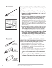
tion. For flame rod sensor runs approximately 100 feet (30 meters)
or greater, use Eclipse part number 21741 coax cable. To achieve the
maximum wiring distance, the shield should not be grounded (keep
in mind that an ungrounded shield provides less protection against
electrical interference).
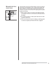
Do not ground the shield to terminal GND.
Note:
Unshielded sensor wiring must not be run in common with other
wires; it must be run in separate conduit. Multiple unshielded
flame sensor wiring must not be run together in a common
conduit or wireway. Use #14 to #18 AWG wire suitable for 90°C
(194°F) and 600 volt insulation, or better grade if required by
the application. Multiple shielded cables can be run in a common
conduit.
INTRODUCTION
7
Sensor Installation
SENSOR WIRING