


Eclipse Bi-Flame v1.8, Instruction Manual 826, 05/03
23
Route ignition wiring a sufficient distance from all sensors and other
low voltage wiring to avoid electrical interference, which may cause
erratic operation of the Bi-Flame system.
Caution:
Do not connect multiple ignition coils in excess of output relay
contact rating
Route communication wiring, using shielded cable, a sufficient
distance from ignition and other high voltage wiring to avoid
electrical interference.
All input power must be single phase 120 VAC, 60/50 Hz selectable,
see page 13. All circuits must have a common 15 amp fuse and
disconnect. The neutral must be grounded. Do not use solid-state
triac output devices in any of the input circuits. 120 VAC wiring
must be at least 90°C 16 AWG minimum and satisfy all applicable
codes.
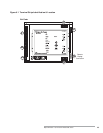
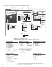
It is possible to wire the system for checking low fire start position
prior to pilot ignition. To use this feature, the low fire start switch
must be connected to the low fire start input (terminal 4 on
terminal strip J1). If this feature is not used, a jumper must be
placed between terminals 1 and 4 on terminal strip J1.
The system can be wired to check for the proof of valve closure
(POVC) switch on the main gas valve prior to start-up and after
the end of the burner cycle.
To use this feature the POVC switch must be connected to the
POVC switch input (terminal 3 on terminal strip J1). If this feature
is not used, a jumper must be placed between terminals 2 on
terminal strip J2 and 3 on terminal strip J1.
The system can be wired to check for high fire position during the
high fire purge portion of the sequence. To use this feature, the
high fire position switch must be connected to the high fire input
(terminal 5 on terminal strip J1). If this feature is not used, a jumper
must be placed between terminals 1 and 5 on terminal strip J1.
The system can be wired to check auxiliary status conditions with
the four auxiliary inputs. To use this feature, the auxiliary input
switches must be wired to the auxiliary inputs (terminals 7,8,9 and
10 on terminal strip J1). If this feature is not used, these inputs
must be connected to 120 VAC.
IGNITION WIRING
COMMUNICATION
WIRING
POWER SUPPLY
LOW FIRE POSITION
INPUT
MAIN VALVE
PROOF
-OF-CLOSURE
HIGH FIRE POSITION
INPUT
AUXILIARY INPUTS