


5-8
Cisco Intrusion Prevention System Sensor CLI Configuration Guide for IPS 7.2
OL-29168-01
Chapter 5 Configuring Virtual Sensors
Adding, Editing, and Deleting Virtual Sensors
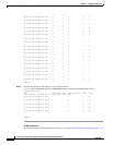
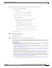
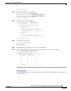
event-action-rules: rules1 default: rules0
anomaly-detection
-----------------------------------------------
anomaly-detection-name: ad1 default: ad0
operational-mode: learn default: detect
-----------------------------------------------
physical-interface (min: 0, max: 999999999, current: 2)
-----------------------------------------------
name: GigabitEthernet0/3
subinterface-number: 0 <defaulted>
-----------------------------------------------
inline-TCP-session-tracking-mode: virtual-sensor default: virtual-sensor
-----------------------------------------------
logical-interface (min: 0, max: 999999999, current: 0)
-----------------------------------------------
-----------------------------------------------
-----------------------------------------------
sensor(config-ana-vir)#
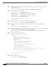
Step 17
Exit analysis engine mode.
sensor(config-ana-vir)# exit
sensor(config-ana)# exit
sensor(config)#
Apply Changes:?[yes]:
Step 18
Press Enter to apply the changes or enter
no
to discard them.
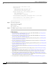
For More Information
•
For the procedure for creating virtual sensors on the ASA 5500-X IPS SSP, see Creating Virtual
Sensors for the ASA 5500-X IPS SSP, page 18-4.
•
For the procedure for creating virtual sensors on the ASA 5585-X IPS SSP, see Creating Virtual
Sensors for the ASA 5585-X IPS SSP, page 19-4.
•
For more information on creating and configuring anomaly detection policies, see Working With
Anomaly Detection Policies, page 9-8.
•
For more information on creating and configuring event action rules policies, see Working With
Event Action Rules Policies, page 8-8.
•
For more information on creating and configuring signature definition policies, see Working With
Signature Definition Policies, page 7-2.
•
For more information about normalization, see Normalization and Inline TCP Evasion Protection
Mode, page 5-4.
•
For more information about inline TCP session tracking mode, see Inline TCP Session Tracking
Mode, page 5-3.
•
For the procedure for pairing inline interfaces, see Configuring Inline Interface Pairs, page 4-17.
Repeat Step 11 for all the inline interface pairs that you want to assign to this virtual sensor.
•
For the procedure for pairing and grouping inline VLANs, see Configuring Inline VLAN Pairs,
page 4-22 and Configuring VLAN Groups, page 4-28. Repeat Step 12 for all inline VLAN pairs or
VLAN groups that you want to assign to this virtual sensor.
•
For the procedure for enabling anomaly detection, see Enabling Anomaly Detection, page 9-8.