


7
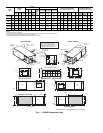
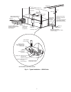
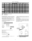
Step 4 — Mounting the Unit — Horizontal units
should be mounted using the factory-installed hangers. Proper
attachment of hanging rods to building structure is critical for
safety. See Fig. 2 and 5. Rod attachments must be able to sup-
port the weight of the unit. See Table 1 for unit operating
weights.
Step 5 — Duct System — Size the duct system to han-
dle the design airflow quietly.
NOTE: Depending on the unit, the fan wheel may have a ship-
ping support installed at the factory. This must be removed
before operating unit.
SOUND ATTENUATION — To eliminate the transfer of
vibration to the duct system, a flexible connector is recom-
mended for both discharge and return air duct connections on
metal duct systems. The supply and return plenums should
include internal duct liner of fiberglass or be made of duct
board construction to maximize sound attenuation of the
blower. Installing the WSHP unit to uninsulated ductwork in an
unconditioned space is not recommended since it will sweat
and adversely affect the unit’s performance.
To reduce air noise, at least one 90 degree elbow could be
included in the supply and return air ducts, provided system
performance is not adversely impacted. The blower speed can
also be changed in the field to reduce air noise or excessive air-
flow, provided system performance is not adversely impacted.
EXISTING DUCT SYSTEM — If the unit is connected to
existing ductwork, consider the following:
• Verify that the existing ducts have the proper capacity to
handle the unit airflow. If the ductwork is too small,
install larger ductwork.
• Check existing ductwork for leaks and repair as
necessary.
NOTE: Local codes may require ventilation air to enter the
space for proper indoor air quality. Hard-duct ventilation may
be required for the ventilating air supply. If hard ducted venti-
lation is not required, be sure that a proper air path is provided
for ventilation air to unit to meet ventilation requirement of the
space.
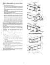
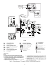
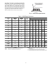
Step 6 — Condensate Drain — Slope the unit to-
ward the drain at a 6.5 mm per 30 cm pitch. See Fig. 6. If it is
not possible to meet the required pitch, install a condensate
pump at the unit to pump condensate to building drain.
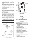
Horizontal units are not internally trapped; therefore an ex-
ternal trap is necessary. Install each unit with its own individual
trap and means to flush or blowout the condensate drain line.
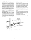
Do not install units with a common trap or vent. For typical
condensate connections see Fig. 7.
NOTE: Never use a pipe size smaller than the connection.
VENTING — Install a vent in the condensate line of any
application that may allow dirt or air to collect in the line. Con-
sider the following:
• Always install a vent where an application requires a
long horizontal run.
• Always install a vent where large units are working
against higher external static pressure and to allow
proper drainage for multiple units connected to the same
condensate main.
• Be sure to support the line where anticipated sagging from
the condensate or when “double trapping” may occur.
• If condensate pump is present on unit, be sure drain con-
nections have a check valve to prevent back flow of con-
densate into other units.
Compressor
Section
Air Handler
Section
B
A
C
E
D
D
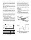
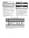
Fig. 5 — Horizontal Hanger Bracket
(Factory Installed)
50RHE UNITS
DIMENSIONS (mm)
ABCDE
006-024 568 1095 619 1095 518
030,036 568 1349 619 1349 518
042,048 568 1577 619 1577 518
060 645 1806 695 1806 594
65 mm Pitch for
Drainage
Pitch Toward
Drain
Drain Connection
Fig. 6 — Horizontal Unit Pitch
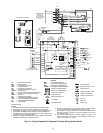
NOTE: Trap should be deep enough to offset maximum unit static
difference. A 102 mm trap is recommended.
Fig. 7 — Trap Condensate Drain