


3
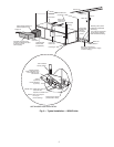
INSPECT UNIT — To prepare the unit for installation, com-
plete the procedures listed below:
1. Compare the electrical data on the unit nameplate with
ordering and shipping information to verify that the
correct unit has been shipped.
2. Verify that the unit is the correct model for the entering
water temperature of the job.
3. Do not remove the packaging until the unit is ready for
installation.
4. Verify that the refrigerant tubing is free of kinks or dents,
and that it does not touch other unit components.
5. Inspect all electrical connections. Be sure connections are
clean and tight at the terminals.
6. Compressors are internally isolated. Compressors
equipped with external spring vibration isolators must
have bolts loosened and shipping clamps removed.
7. Remove any blower support cardboard from inlet of the
blower.
8. Locate and verify any accessory kit located in compressor
section.
9. Remove any access panel screws that may be difficult to
remove once unit is installed.
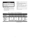
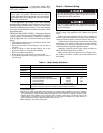
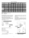
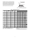
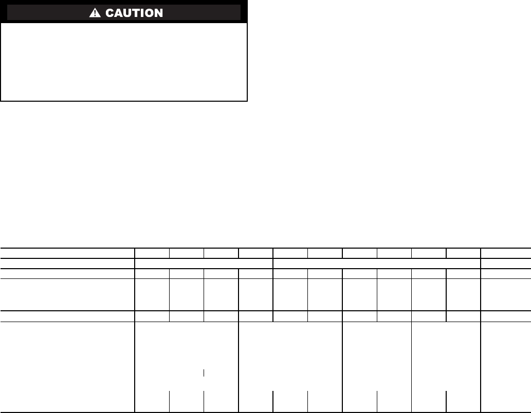
Table 1 — Physical Data — Aquazone™ 50RHE006-060 Units
LEGEND
PSC — Permanent Split Capacitor
NOTES:
1. All units have spring compressor mountings, TXV (thermostatic expan-
sion valve) expansion devices, and
1
/
2
-and
3
/
4
-in. electrical knockouts.
2. Size 048 available as high-static unit.
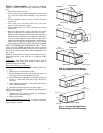
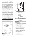
DO NOT store or install units in corrosive environments or
in locations subject to temperature or humidity extremes
(e.g., attics, garages, rooftops, etc.). Corrosive conditions
and high temperature or humidity can significantly reduce
performance, reliability, and service life. Always move
units in an upright position. Tilting units on their sides may
cause equipment damage.
UNIT 50RHE 006 009 012 015 019 024 030 036 042 048 060
COMPRESSOR (1 each) Rotary Reciprocating Scroll
FACTORYCHARGE R-407C (kg) 0.34 0.37 0.37 0.68 0.88 0.91 1.19 1.36 1.19 1.59 2.41
PSC FAN MOTOR AND BLOWER
FanMotor Type/Speeds PSC/3 PSC/3 PSC/3 PSC/3 PSC/3 PSC/3 PSC/3 PSC/3 PSC/3 PSC/3 PSC/3
Fan Motor (Hp) [w]
1
/
25
[30]
1
/
10
[75]
1
/
10
[75]
1
/
6
[124]
1
/
5
[150]
1
/
3
[250]
1
/
2
[373]
3
/
4
[560]
3
/
4
[560]
3
/
4
[560] 1[746]
Blower Wheel Size (D x W) (mm) 127 x 127 127 x 127 152 x 127 152 x 127 152 x 127 152 x 127 152 x 127 254 x 254 254 x 254 254 x 254 279 x 254
WATER CONNECTION SIZE (in.) (FPT)
1
/
2
1
/
2
1
/
2
3
/
4
3
/
4
3
/
4
3
/
4
3
/
4
11 1
HORIZONTAL
Air Coil
Dimensions (H x W) (mm) 254 x 406 406 x 406 457 x 559 457 x 787 508 x 889
Total Face Area (m
2
) 0.103 0.165 0.255 0.360 0.452
Tube Size (mm) 9.5
9.5 9.5 9.5 9.5
Distance Between Fins (mm) 2.2 2.2 2.2 2.2 2.7
Number of Rows 23 3 3 3 4
Filter Standard Throwaway
(Qty — Size, mm)
1 — 254 x 508 1 — 406 x 508 1 — 457 x 610 2 — 457 x 457
1 — 305 x 508
1 — 635 x 508
Weight 25.4-mm (kg)
Operating 50.0 50.9 55.0 66.8 76.8 87.7 99.5 104.1 116.8 121.4 146.8
Packaged 54.5 55.5 59.5 71.4 81.4 92.3 105.0 109.5 122.3 126.8 153.6