


21
Antifreeze — In areas where entering loop temperatures
drop below 4.4 C or where piping will be routed through areas
subject to freezing, antifreeze is needed.
Alcohols and glycols are commonly used as antifreeze
agents. Freeze protection should be maintained to 8.3 K below
the lowest expected entering loop temperature. For example, if
the lowest expected entering loop temperature is –1.1 C, the
leaving loop temperature would be –5.6 to –3.9 C. Therefore, the
freeze protection should be at –9.4 C (–1.1 C –8.3 C = –9.4 C).
Calculate the total volume of fluid in the piping system. See
Table 11. Use the percentage by volume in Table 12 to deter-
mine the amount of antifreeze to use. Antifreeze concentration
should be checked from a well mixed sample using a hydrome-
ter to measure specific gravity.
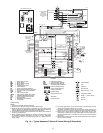
FREEZE PROTECTION SELECTION — The –1.1 C FP1
factory setting (water) should be used to avoid freeze damage
to the unit.
Once antifreeze is selected, the JW3 jumper (FP1) should
be clipped on the control to select the low temperature (anti-
freeze 13 F) set point to avoid nuisance faults.
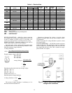
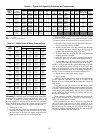
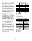
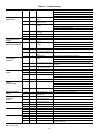
Table 11 — Approximate Fluid Volume (L)
per 30 m of Pipe
LEGEND
NOTE: Volume of heat exchanger is approximately 3.78 liters.
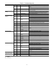
Table 12 — Antifreeze Percentages by Volume
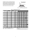
Cooling Tower/Boiler Systems — These systems typ-
ically use a common loop temperature maintained at 15.6 to
32.2 C. Carrier recommends using a closed circuit evaporative
cooling tower with a secondary heat exchanger between the
tower and the water loop. If an open type cooling tower is used
continuously, chemical treatment and filtering will be necessary.
The optional cupronickel heat exchanger must also be used in
this case.
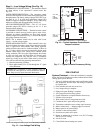
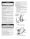
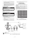
Ground Coupled, Closed Loop and Plateframe
Heat Exchanger Well Systems —
These systems al-
low water temperatures from –1.1 to 43.3 C. The external loop
field is divided up into 51 mm polyethylene supply and return
lines. Each line has valves connected in such a way that upon
system start-up, each line can be isolated for flushing using
only the system pumps. Locate air separation in the piping sys-
tem prior to the fluid re-entering the loop field.
OPERATION
Power Up Mode —
The unit will not operate until all the
inputs, terminals and safety controls are checked for normal
operation.
NOTE: The compressor will have a 5-minute anti-short cycle
upon power up.
Units with Aquazone™ Complete C Control
STANDBY — Y and W terminals are not active in standby
mode, however the O and G terminals may be active, depend-
ing on the application. The compressor will be off.
COOLING — Y and O terminals are active in Cooling mode.
After power up, the first call to the compressor will initiate a
5 to 80 second random start delay and a 5-minute anti-short
cycle protection time delay. After both delays are complete, the
compressor is energized.
NOTE: On all subsequent compressor calls the random start
delay is omitted.
HEATING STAGE 1 — Terminal Y is active in heating
stage 1. After power up, the first call to the compressor will
initiate a 5 to 80 second random start delay and a 5-minute
anti-short cycle protection time delay. After both delays are
complete, the compressor is energized.
NOTE: On all subsequent compressor calls the random start
delay is omitted.
HEATING STAGE 2 — To enter Stage 2 mode, terminal W is
active (Y is already active). Also, the G terminal must be ac-
tive or the W terminal is disregarded. The compressor relay
will remain on and EH1 is immediately turned on. EH2 will
turn on after 10 minutes of continual stage 2 demand.
NOTE: EH2 will not turn on (or if on, will turn off) if FP1 tem-
perature is greater than 7.2 C and FP2 is greater than 43.3 C.
EMERGENCY HEAT — In emergency heat mode, terminal
W is active while terminal Y is not. Terminal G must be active
or the W terminal is disregarded. EH1 is immediately turned
on. EH2 will turn on after 5 minutes of continual emergency
heat demand.
Units with Aquazone Deluxe D Control
STANDBY/FAN ONLY — The compressor will be off. The
Fan Enable, Fan Speed, and reversing valve (RV) relays will be
on if inputs are present. If there is a Fan 1 demand, the Fan
Enable will immediately turn on. If there is a Fan 2 demand,
the Fan Enable and Fan Speed will immediately turn on.
NOTE: DIP switch 5 on S1 does not have an effect upon Fan 1
and Fan 2 outputs.
HEATING STAGE 1 — In Heating Stage 1 mode, the Fan
Enable and Compressor relays are turned on immediately.
Once the demand is removed, the relays are turned off and the
control reverts to Standby mode. If there is a master/slave or
dual compressor application, all compressor relays and related
functions will operate per their associated DIP switch 2 setting
on S1.
HEATING STAGE 2 — In Heating Stage 2 mode, the Fan
Enable and Compressor relays are remain on. The Fan Speed
relay is turned on immediately and turned off immediately
once the demand is removed. The control reverts to Heating
Stage 1 mode. If there is a master/slave or dual compressor
application, all compressor relays and related functions will op-
erate per their associated DIP switch 2 setting on S1.
HEATING STAGE 3 — In Heating Stage 3 mode, the Fan
Enable, Fan Speed and Compressor relays remain on. The EH1
output is turned on immediately. With continuing Heat Stage 3
demand, EH2 will turn on after 10 minutes. EH1 and EH2 are
turned off immediately when the Heating Stage 3 demand is re-
moved. The control reverts to Heating Stage 2 mode.
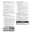
IMPORTANT: All alcohols should be pre-mixed and
pumped from a reservoir outside of the building or
introduced under water level to prevent fuming.
PIPE DIAMETER (in.) VOLUME (l)
Copper 1 15.5
1.25 24.2
1.5 34.8
Rubber Hose 1 14.7
Polyethylene
3
/
4
IPS SDR11 10.6
1 IPS SDR11 17.0
1
1
/
4
IPS SDR11 30.0
1
/
2
IPS SDR11 41.2
2 IPS SDR11 68.1
1
1
/
4
IPS SCH40 31.4
1
1
/
2
IPS SCH40 41.2
2 IPS SCH40 64.3
IPS — Internal Pipe Size
SCH — Schedule
SDR — Standard Dimensional Ratio
ANTIFREEZE
MINIMUM TEMPERATURE FOR
FREEZE PROTECTION (C)
–12 –9 –7 –4
Methanol (%) 25 21 16 10
100% USP Food Grade
Propylene Glycol (%)
38 30 22 15