


22
Output EH2 will be off if FP1 is greater than 7.2 C and FP2
(when shorted) is greater than 43.3 C during Heating Stage 3
mode. This condition will have a 30-second recognition time.
Also, during Heating Stage 3 mode, EH1, EH2, Fan Enable,
and Fan Speed will be ON if G input is not active.
EMERGENCY HEAT — In Emergency Heat mode, the Fan
Enable and Fan Speed relays are turned on. The EH1 output is
turned on immediately. With continuing Emergency Heat de-
mand, EH2 will turn on after 5 minutes. Fan Enable and Fan
Speed relays are turned off after a 60-second delay. The control
reverts to Standby mode.
Output EH1, EH2, Fan Enable, and Fan Speed will be ON if
the G input is not active during Emergency Heat mode.
COOLING STAGE 1 — In Cooling Stage 1 mode, the Fan
Enable, compressor and RV relays are turned on immediately.
If configured as stage 2 (DIP switch set to OFF) then the com-
pressor and fan will not turn on until there is a stage 2 demand.
The fan Enable and compressor relays are turned off immedi-
ately when the Cooling Stage 1 demand is removed. The con-
trol reverts to Standby mode. The RV relay remains on until
there is a heating demand. If there is a master/slave or dual
compressor application, all compressor relays and related func-
tions will track with their associated DIP switch 2 on S1.
COOLING STAGE 2 — In Cooling Stage 2 mode, the Fan
Enable, compressor and RV relays remain on. The Fan Speed
relay is turned on immediately and turned off immediately
once the Cooling Stage 2 demand is removed. The control re-
verts to Cooling Stage 1 mode. If there is a master/slave or dual
compressor application, all compressor relays and related func-
tions will track with their associated DIP switch 2 on S1.
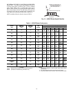
NIGHT LOW LIMIT (NLL) STAGED HEATING — In NLL
staged Heating mode, the override (OVR) input becomes ac-
tive and is recognized as a call for heating and the control will
immediately go into a Heating Stage 1 mode. With an addition-
al 30 minutes of NLL demand, the control will go into Heating
Stage 2 mode. With another additional 30 minutes of NLL
demand, the control will go into Heating Stage 3 mode.
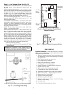
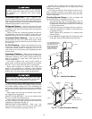
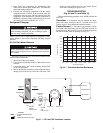
SYSTEM TEST
System testing provides the ability to check the control
operation. The control enters a 20-minute Test mode by
momentarily shorting the test pins (see Fig. 9-12). All time
delays are reduced by a factor of 15.
Test Mode — To enter Test mode on C or D controls, cycle
the power 3 times within 60 seconds. The LED (light-emitting
diode) will flash a code representing the last fault when enter-
ing the Test mode. The alarm relay will also power on and off
during Test mode. See Tables 13 and 14. To exit Test mode,
short the terminals for 3 seconds or cycle the power 3 times
within 60 seconds.
NOTE: Deluxe D Control has a flashing code and alarm relay
cycling code that will both have the same numerical label.
For example, flashing code 1 will have an alarm relay cycling
code 1. Code 1 indicates the control has not faulted since the
last power off to power on sequence.
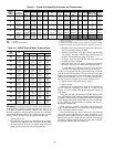
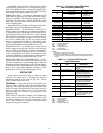
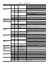
Table 13 — C Control Current LED Status
and Alarm Relay Operations
LEGEND
NOTES:
1. Slow flash is 1 flash every 2 seconds.
2. Fast flash is 2 flashes every 1 second.
3. EXAMPLE: “Flashing Code 2” is represented by 2 fast flashes followed by
a 10-second pause. This sequence will repeat continually until the fault is
cleared.
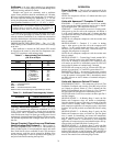
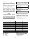
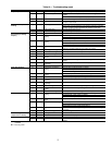
Table 14 — C Control LED Code and
Fault Descriptions
LEGEND
LED STATUS DESCRIPTION OF OPERATION ALARM RELAY
On
NormalMode Open
Normal Mode with
PM Warning
Cycle
(closed 5 sec.,
Open25 sec.)
Off C Control is non-functional Open
Slow Flash Fault Retry Open
Fast Flash Lockout Closed
Slow Flash Over/Under Voltage Shutdown
Open
(Closed after
15 minutes)
Flashing Code 1 Test Mode — No fault in memory Cycling Code 1
Flashing Code 2 Test Mode — HP Fault in memory Cycling Code 2
Flashing Code 3 Test Mode — LP Fault in memory Cycling Code 3
Flashing Code 4 Test Mode— FP1 Fault in memory CyclingCode 4
Flashing Code 5 Test Mode— FP2 Fault in memory CyclingCode 5
Flashing Code 6 Test Mode — CO Fault in memory Cycling Code 6
Flashing Code 7
Test Mode — Over/Under
shutdown in memory
Cycling Code 7
Flashing Code 8 Test Mode— PM inmemory Cycling Code 8
Flashing Code 9
Test Mode — FP1/FP2
Swapped Fault in memory
Cycling Code 9
CO — Condensate Overflow
FP — Freeze Protection
HP — High Pressure
LED — Light-Emitting Diode
LP — Low Pressure
PM — Performance Monitor
LED
CODE
FAULT DESCRIPTION
1 No fault in memory There has been no fault since
the last power-down to power-up
sequence
2 High-Pressure Switch HP Open Instantly
3 Low-Pressure Switch LP open for 30 continuous sec-
onds before or during a call
(bypassed for first 60 seconds)
4 Freeze Protection Coax
—FP1
FP1 below Temp limit for 30 con-
tinuous seconds (bypassed for
first 60 seconds of operation)
5 Freeze Protection Air Coil
—FP2
FP2 below Temp limit for 30 con-
tinuous seconds (bypassed for
first 60 seconds of operation)
6 Condensate overflow Sense overflow (grounded) for
30 continuous seconds
7
(Autoreset)
Over/Under Voltage
Shutdown
"R" power supply is <19VAC or
>30VAC
8 PM Warning PerformanceMonitorWarning
has occurred.
9 FP1 and FP2 Thermistors
are swapped
FP1 temperature is higher than
FP2 inheating/test mode,orFP2
temperature is higher thanFP1
in cooling/test mode.
FP — Freeze Protection
HP — High Pressure
LED — Light-Emitting Diode
LP — Low Pressure
PM — Performance Monitor