


16
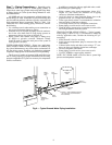
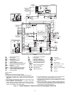
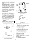
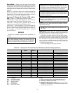
Step 9 — Low Voltage Wiring (See Fig. 15)
THERMOSTAT CONNECTIONS — The thermostat should
be wired directly to the Aquazone™ control board. See
Fig. 9-12.
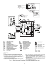
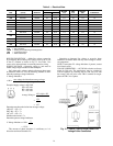
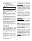
WATER FREEZE PROTECTION — The Aquazone control
allows the field selection of source fluid freeze protection points
through jumpers. The factory setting of jumper JW3 (FP1) is set
for water at –1.1 C. In earth loop applications, jumper JW3
should be clipped to change the setting to –10.6 C when using
antifreeze in colder earth loop applications. See Fig. 16.
AIR COIL FREEZE PROTECTION — The air coil freeze
protection jumper JW2 (FP2) is factory set for –1.1 C and
should not need adjusting.
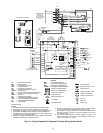
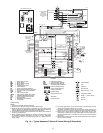
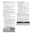
ACCESSORY CONNECTIONS — Terminal A on the control
is provided to control accessory devices such as water valves,
electronic air cleaners, humidifiers, etc. This signal operates
with the compressor terminal. See Fig. 17. Refer to the specific
unit wiring schematic for details.
NOTE: The A terminal should only be used with 24-volt
signals — not line voltage signals.
WATER SOLENOID VALVES — Water solenoid valves may
be used on primary/secondary pump and ground water installa-
tions. A typical well water control valve wiring approach,
which can limit waste water in a lockout condition, is shown in
Fig. 17. A slow closing valve may be required to prevent water
hammer. When using a slow closing valve, consider special
wiring conditions. The valve takes approximately 60 seconds
to open (very little water will flow before 45 seconds) and it
activates the compressor only after the valve is completely
opened by closing its end switch. When wired as shown, the
valve will have the following operating characteristics:
1. Remain open during a lockout
2. Draw approximately 25 to 35 VA through the “Y” signal
of the thermostat.
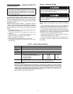
PRE-START-UP
System Checkout —
When the installation is complete,
follow the System Checkout procedure outlined below before
starting up the system. Be sure:
1. Voltage is within the utilization range specifications of the
unit compressor and fan motor and voltage is balanced
for 3-phase units.
2. Fuses, breakers and wire are correct size.
3. Low voltage wiring is complete.
4. Piping and system flushing is complete.
5. Air is purged from closed loop system.
6. System is balanced as required. Monitor if necessary.
7. Isolation valves are open.
8. Water control valves or loop pumps are wired.
9. Condensate line is open and correctly pitched.
10. Transformer switched to lower voltage tap if necessary.
11. Blower rotates freely — shipping support is removed.
12. Blower speed is on correct setting.
13. Air filter is clean and in position.
14. Service/access panels are in place.
15. Return air temperature is between 4.4 to 26.7 C heating
and 10 to 43.3 C cooling.
16. Air coil is clean.
17. Control field selected settings are correct.
IMPORTANT: Connecting a water solenoid valve can
overheat the anticipators of electromechanical thermo-
stats. Only use relay based electronic thermostats.
NOTE: Low voltage connector may be removed for easy installation.
Fig. 15 — Low Voltage Field Wiring
Off On
Comp
Relay
FP1 Low Temp
FP2 Low Temp
JW3
JW2
Test
BR BRG
CCG
CC
Y
C
R
Micro
Y
W
O
G
R
C
AL1
AL2
A
P1
JW1-AL2 DRY
Alarm
Relay
1
12
P2
HP
HP
LP
LP
FP1
FP1
FP2
FP2
RV
RV
CO
CO
Status
LED
CO
P3
1
4
EH1
EH2
24Vdc
CLIP JW2-FP2
JUMPER FOR
ANTI-FREEZE
SYSTEMS
CLIP JW3
FOR
FREEZE
PROTECT
CLIP
FOR DRY
CONTACT
Typical
Water
Valve
C
A
24 VAC
Terminal Strip P2
AQUAZONE CONTROL (C Control Shown)
Fig. 16 — Typical Aquazone Control Board
Jumper Locations
Fig. 17 — Typical D Control Accessory Wiring