


25
5. Read liquid line temperature on thermometer; then
subtract from bubble point temperature. The difference
equals subcooling temperature.
6. Compare the subcooling temperature with the normal
temperature listed in Table 9. If the measured liquid line
temperature does not agree with the required liquid line
temperature, ADD refrigerant to raise the temperature or
REMOVE refrigerant (using standard practices) to lower
the temperature (allow a tolerance of ± 1.7° C).
Refrigerant Charging
NOTE: Do not vent or depressurize unit refrigerant to atmo-
sphere. Remove and reclaim refrigerant following accepted
practices.
Air Coil Fan Motor Removal
Disconnect motor power wires from motor terminals before
motor is removed from unit.
1. Shut off unit main power supply.
2. Loosen bolts on mounting bracket so that fan belt can be
removed.
3. Loosen and remove the 2 motor mounting bracket bolts
on left side of bracket.
4. Slide motor/bracket assembly to extreme right and lift out
through space between fan scroll and side frame. Rest
motor on a high platform such as a step ladder. Do not
allow motor to hang by its power wires.
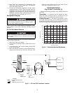
TROUBLESHOOTING
(Fig. 20 and 21, and Table 16)
When troubleshooting problems with a WSHP, consider the
following.
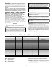
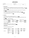
Thermistor — A thermistor may be required for single-
phase units where starting the unit is a problem due to low
voltage. See Fig. 20 for thermistor nominal resistance.
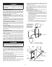
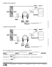
Control Sensors — The control system employs 2 nom-
inal 10,000 ohm thermistors (FP1 and FP2) that are used for
freeze protection. Be sure FP1 is located in the discharge fluid
and FP2 is located in the air discharge. See Fig. 21.
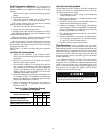
To prevent personal injury, wear safety glasses and gloves
when handling refrigerant. Do not overcharge system —
this can cause compressor flooding.
Before attempting to remove fan motors or motor mounts,
place a piece of plywood over evaporator coils to prevent
coil damage.
0.0
10.0
20.0
30.0
40.0
50.0
60.0
70.0
80.0
90.0
0.0 20.0 40.0 60.0 80.0 100.0 120.0 140.0
Temperature (degF)
Resistance (kOhm)
Fig. 20 — Thermistor Nominal Resistance
SUCTION
COMPRESSOR
DISCHARGE
COAX
EXPANSION
VALVE
FP2
FP1
LIQUID
LINE
WATERIN
WATEROUT
CONDENSATE
OVERFLOW
(CO)
AIR COIL
FREEZE
PROTECTION
WATER
COIL
PROTECTION
THERMISTOR
(°F)
(°F)
AIR
COIL
AIRFLOW
AIRFLOW
LEGEND
Fig. 21 — FP1 and FP2 Thermistor Location
COAX — Coaxial Heat Exchanger
Airflow
Refrigerant Liquid Line Flow