


12
FAN ENABLE
RELAY
POWER SUPPLY
REFER TO
DATAPLATE
USE COPPER
CONDUCTORS
ONLY
SEE NOTE 8
EARTH (GRD)
N (NEUTRAL)
L
1
2
3
4
5
6
G/Y
G/Y
YEL
STARTASSIST
(
WHEN NEEDED
)
RED
BLK
BLK
YEL
RED BLU
68
24
CR
COMPRESSOR
RED* BLU*
RED
CAP
S
C
R
BLK
24
BR1
68
YEL
BLK
YEL OR WHT
BLK
BLU
RED
BMC
BRN
BR2
NO COM
NC
SEE NOTE 3
TRANS
BLK
RED
(
220V
)
ORG
(
240V
)
24V
CB
YEL
BLU
COMPONENT LOCATION
SIZES: 015-060
CR
BR2
BR1
(CAP TUBE
UNITS) OR
SEE NOTE 5
TYPICAL HEAT
PUMPT-STAT
O
G
R
C
XI
COMPR.
FAN
24VAC
ALARM
SEE NOTE 6 FOR
DRY CONTACT
FOR ALARM
Y1
O/W2
G
R
C
AL1
W1
AL2
A
P3
R
C
ALARM
RELAY
SEE
NOTE 6
JW1
LP
STATUS
TEST
FAULT
G
DXM
MICROPROCESSOR
CONTROL LOGIC
SEE
NOTE 7
TEST
PINS
1
2
RV RELAY
3
4
5
6
7
8
9
10
HP
LOC
FP1
RV
CO
P7
P6
CCG
24V
DC
EH1
EH2
RED
BLU
GRY
GRY
HP
LOC
FP1
FP2
BRN
BRN
ORG
YEL
VIO
VIO
VIO
SEE NOTE 4
(TXV UNITS)
NSB
ESD
OVR
H
P2
C
R
Y2
P1
R
R
COM
NC2
NO2
COM
NC1
NO1
RELAY
ACC1
RELAY
ACC2
JW2
FP2
JW3
FP1
LOW
LOW
N.O.
ACC1
FUNCTIONS
ACC2
FUNCTIONS
H:HI FAN/DEHUMID
NOT USED
OFFON
S2
DIP SWITCH PACKAGE
S1
DIP SWITCH PACKAGE
OFFON
PM: DISABLE/ENABLE
UNIT STAGE:2/1
T’STAT: HEAT COOL/HEAT PUMP
RV ON B/RV ON 0
DEHUMID/NORMAL
NOT USED
BOILERLESS: ENABLE/DISABLE
BOILERLESS:40°F/50°F
SEE
NOTE 4
FP2
CC
1
2
3
4
5
6
7
8
1
2
3
4
5
6
7
8
1
2
3
4
5
6
7
8
CO
YEL
CR
1
MV*
Y
R
RED
BLK*
HWTS
BLK*
GRY
BR2
SEE
NOTE 7
BRN
BRN
1
0
COM
NO NC
COM
NO
FAN
SPEED
RELAY
COM2 COM1
RCS
CS
COMPR
RELAY
GRY
RED
RED
JW4
AL2 DRY
COOLING
COMMON
BRN*
2
RED*
BR1
12
SIZES:006, 009, 012
CR
BR1
BR2
POWER
DISTRIBUTION
BLOCK
PB
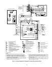
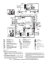
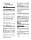
AL — Alarm Relay Contacts
BM — Blower Motor
BMC — Blower Motor Capacitor
BR — Blower Relay
CAP — Compressor Capacitor
CB — Circuit Breaker
CO — Sensor, Condensate Overflow
FP1 — Sensor, Water Coil Freeze Protection
FP2 — Sensor, Air Coil Freeze Protection
GND — Ground
HP — High-Pressure Switch
HWTS — High (Leaving) Water Temp Switch
JW — Clippable Field Selection Jumper
LOC — Loss of Charge Pressure Switch
MV — Motorized Valve
*Optional wiring.
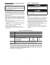
NOTES:
1. Compressor thermally protected internally.
2. All wiring to the unit must comply with NEC and local codes.
3. Transformer is wired to 240 v (ORG) lead for 240/50/1 units,
switch RED and ORG leads to PB(1) and insulate ORG lead for
220/50/1.
4. FP1 thermistor provides freeze protection for water. When using
antifreeze solutions, cut JW3 jumper.
5. Check installation wiring information for specific thermostat
hookup. Refer to thermostat installation instructions for wiring to
the unit. Thermostat wiring must be “Class 1” and voltage rating
equal to or greater than unit supply voltage.
LEGEND
P1 — Field Wiring Terminal Block
PB — Power Block
PM — Performance Monitor
PSC — Permanent Split Capacitor
RVS — Reversing Valve Solenoid
TRANS — Transformer Optional Wiring
Field Line Voltage Wiring
Field Low Voltage Wiring
Printed Circuit Trace
Optional Wiring
Relay/Contactor Coil
Thermistor
Condensate Pan
LED
Solenoid Coil
RelayContacts—N.O.
Temperature Switch
Switch — Loss of Charge
Ground
Wire Nut
G
6. 24-v alarm signal shown. For dry alarm contact, cut JW4 jumper,
and dry contact will be available between AL1 and AL2.
7. Transformer secondary ground via microprocessor board stand-
offs and screws to control box. (Ground available from top two
standoffs as shown.)
8. Blower motor is factory wired for medium and high speeds. For
any other combination of speeds, at the motor attach black wire
to the higher of the two desired speed taps, and the blue wire to
the lower of the two desired speed taps.
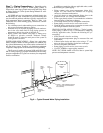
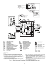
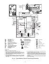
Fig. 11 — Typical Aquazone™ Deluxe D Control Wiring (Single-Phase Unit)