


6
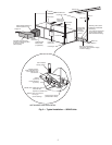
Step 3 — Unit Location — The following guidelines
should be considered when choosing a location for a WSHP
unit:
• Units are for indoor use only
• Locate in areas where ambient temperatures are between
4.4 C and 37.8 C and relative humidity is no greater than
75%
• Provide sufficient space for water, electrical and duct
connections
• Locate unit in an area that allows easy access and
removal of filter and access panels
• Allow enough space for service personnel to perform
maintenance
• Return air must be able to freely enter the space if unit
needs to be installed in a confined area such as a closet
NOTE: Correct placement of the horizontal unit can play an
important part in minimizing sound problems. Since duct-
work is normally applied to these units, the unit can be
placed so that the principal sound emission is outside the oc-
cupied space in sound-critical applications. A fire damper
may be required by the local code if a fire wall is penetrated.
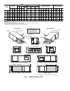
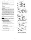
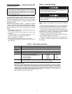
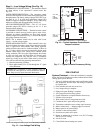
FIELD CONVERSION OF DISCHARGE AIR — The dis-
charge air of the 50RHE horizontal units can be converted
between side and back discharge in the field. The conversion
process is the same for right and left return configurations. See
Fig. 3 and 4.
NOTE: It is not possible to convert return air between left or
right return models in the field due to refrigerant piping
changes.
Preparation
— The unit should be on the ground in a well lit
area for conversion. Hung units should be taken down to
ground level before converting.
Side to Back Discharge Conversion
1. Remove screws to free the top and discharge panels. See
Fig. 3.
2. Remove the access panel and set aside.
3. Lift the discharge panel from side of unit and rotate it to
back using care not to damage blower wiring.
4. Check blower wire routing and connections for excessive
tension or contact with sheet metal edges. Re-route if
necessary.
5. Check refrigerant tubing for contact with other compo-
nents. Adjust if necessary.
6. Reinstall top panel using screws set aside in Step 1.
NOTE: Location for some screws at bottom of discharge panel
may have to be changed.
7. Manually spin fan wheel to check for obstructions.
Adjust for any obstruction found.
8. Replace access panel.
Back to Side Discharge Conversion
— Follow instructions
above for Side to Back Discharge Conversion, noting the
panels would be reversed.
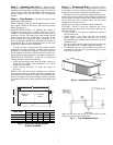
ReturnAir
Remove Screws
ReturnAir
Rotate
Move to Side
Side Discharge
ReturnAir
DischargeAir
Drain
Back Discharge
Replace Screws
Water
Connection End
Water
Connection End
Water
Connection End
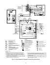
Fig. 3 — Conversion Left Return,
Side Discharge to Back Discharge
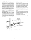
Water
Connection End
Supply
Duct
ReturnAir
Water
Connection End
Drain
ReturnAir
DischargeAir
Side Discharge
Back Discharge
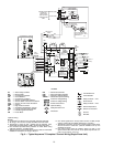
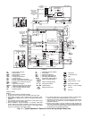
Fig. 4 — Conversion Right Return,
Side Discharge to Back Discharge