


20
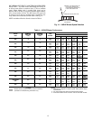
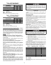
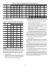
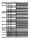
Table 9 — Typical Unit Operating Pressures and Temperatures
LEGEND NOTES:
1. Based on nominal 54 L/s per kW airflow and 21° C EATheating and 26.7/
194° C EAT cooling.
2. Coolingair and water numbers can vary greatly withchanges inhumidity.
3. Subcooling is based upon the head pressure at compressor service port.
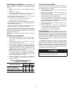
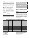
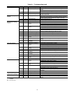
Table 10 — 50RHE Coaxial Water Pressure Drop
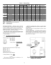
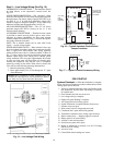
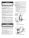
Flushing — Once the piping is complete, units require final
purging and loop charging. A flush cart pump of at least 1.5 hp
(1.12 kW) is needed to achieve adequate flow velocity in
the loop to purge air and dirt particles from the loop. Flush the
loop in both directions with a high volume of water at a high
velocity. Follow the steps below to properly flush the loop:
1. Verify power is off.
2. Fill loop with water from hose through flush cart before
using flush cart pump to ensure an even fill. Do not allow
the water level in the flush cart tank to drop below the
pump inlet line to prevent air from filling the line.
3. Maintain a fluid level in the tank above the return tee to
avoid air entering back into the fluid.
4. Shutting off the return valve that connects into the flush
cart reservoir will allow 345 kPa surges to help purge air
pockets. This maintains the pump at 345 kPa.
5. To purge, keep the pump at 345 kPa until maximum
pumping pressure is reached.
6. Open the return valve to send a pressure surge through
the loop to purge any air pockets in the piping system.
7. A noticeable drop in fluid level will be seen in the flush
cart tank. This is the only indication of air in the loop.
NOTE: If air is purged from the system while using a 254 mm
PVC flush tank, the level drop will only be 25 to 51 mm since
liquids are incompressible. If the level drops more than this,
flushing should continue since air is still being compressed in
the loop. If level is less than 25 to 51 mm, reverse the flow.
8. Repeat this procedure until all air is purged.
9. Restore power.
Antifreeze may be added before, during or after the flushing
process. However, depending on when it is added in the
process, it can be wasted. Refer to the Antifreeze section for
more detail.
Loop static pressure will fluctuate with the seasons. Pres-
sures will be higher in the winter months than during the warm-
er months. This fluctuation is normal and should be considered
when charging the system initially. Run the unit in either heat-
ing or cooling for several minutes to condition the loop to a
homogenous temperature.
When complete, perform a final flush and pressurize the
loop to a static pressure of 275 to 345 kPa for winter months or
105 to 135 kPa for summer months.
After pressurization, be sure to remove the plug from the
end of the loop pump motor(s) to allow trapped air to be
discharged and to ensure the motor housing has been flooded.
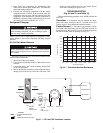
Be sure the loop flow center provides adequate flow through
the unit by checking pressure drop across the heat exchanger.
Compare the results to the data in Table 10.
ENTERING
WATER
TEMP (C)
(EWT)
WATER
FLOW
(l/s per kW)
COOLING HEATING
Suction
Pressure
(kPa)
Discharge
Pressure
(kPa)
Super-
heat
(C)
Sub-
cooling
(C)
Water Temp
Rise
(C)
Air Temp
Drop (C)
DB
Suction
Pressure
(kPa)
Discharge
Pressure
(kPa)
Super-
heat
(C)
Sub-
cooling
(C)
Water Temp
Drop (C) DB
Air
Temp
Rise (C)
–1
0.027 225-254 269-314 14-22 7-11 12-13 12-14 102-117 499-556 7- 9 1-2 4-5 8-11
0.041 222-251 239-284 14-22 6-10 7- 9 12-14 111-129 514-571 7- 9 1-2 3-4 9-12
0.054 219-248 209-254 14-22 6- 9 3- 6 12-14 120-138 529-586 7- 9 1-2 2-3 9-12
10
0.027 225-254 374-463 7-11 6-10 11-13 11-14 150-179 538-628 6- 9 1-3 6-7 13-16
0.041 222-251 359-425 7-11 5- 9 7- 8 11-14 158-185 553-643 6- 9 1-3 4-5 13-17
0.054 219-248 344-413 7-11 4- 8 4- 7 11-14 164-194 568-658 6- 9 1-3 3-4 14-17
21
0.027 225-254 535-592 5- 9 4- 8 11-12 11-13 212-245 613-688 8-11 1-3 8-9 16-19
0.041 222-251 502-556 5- 9 4- 7 7- 9 11-13 218-254 628-712 8-11 1-3 5-6 17-21
0.054 219-248 472-523 5- 9 4- 7 4- 7 11-13 227-263 643-724 8-11 1-3 3-4 17-21
32
0.027 225-254 685-750 5- 9 4- 8 10-12 9-13 254-284 658-777 10-16 1-3 8-9 18-22
0.041 222-251 652-721 5- 9 4- 7 6- 8 9-13 269-299 673-792 10-16 1-3 6-7 18-23
0.054 219-248 622-688 5- 9 4- 7 3- 6 9-13 284-314 688-807 10-16 1-3 4-5 19-23
43
0.027 231-260 837-957 4- 8 6-14 9-11 8-11
0.041 228-257 807-927 4- 8 6-13 5- 7 8-11
0.054 225-254 777-897 4- 8 6-12 3- 6 8-11
DB — Dry Bulb
EAT — Entering Air Temperature
UNIT
50RHE
L/S
PRESSURE DROP (kPa)
0° C 10° C 20° C 30° C
006
0.047 6.0 5.4 5.1 4.8
0.071 8.4 7.8 7.2 6.9
0.095 14.1 13.2 12.0 11.7
009
0.071 8.1 7.5 6.9 6.6
0.107 12.0 11.1 10.5 9.9
0.139 23.9 22.4 20.9 20.0
012
0.095 19.1 17.9 16.7 16.1
0.145 41.3 38.9 36.2 34.7
0.189 66.1 61.9 57.7 55.0
015
0.114 16.7 15.5 14.7 14.1
0.164 32.6 30.5 28.7 27.2
0.221 55.9 52.3 48.7 46.3
019
0.142 12.9 12.0 11.1 10.8
0.215 23.0 21.5 20.3 19.1
0.284 45.4 42.5 39.8 37.7
024
0.189 13.8 12.6 11.7 11.4
0.284 28.7 26.9 25.1 23.9
0.379 47.8 44.9 41.9 39.8
030
0.237 9.9 9.0 8.4 8.1
0.347 17.0 15.8 14.7 14.1
0.473 26.9 25.4 23.6 22.4
036
0.284 7.8 7.2 6.9 6.6
0.426 15.0 13.8 12.9 12.3
0.568 23.9 22.4 20.9 20.0
042
0.331 9.9 9.3 8.7 8.4
0.498 19.7 18.5 17.0 16.4
0.663 31.1 29.3 27.5 26.0
048
0.379 14.1 13.2 12.3 11.7
0.568 26.9 25.4 23.6 22.4
0.757 44.0 41.0 38.3 36.5
060
0.473 33.5 31.4 29.3 27.8
0.713 58.3 54.4 50.8 48.4
0.947 88.5 82.8 77.1 73.3