


19
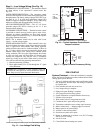
Scroll Compressor Rotation — It is important to be
certain compressor is rotating in the proper direction. To
determine whether or not compressor is rotating in the proper
direction:
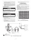
1. Connect service gages to suction and discharge pressure
fittings.
2. Energize the compressor.
3. The suction pressure should drop and the discharge
pressure should rise, as is normal on any start-up.
If the suction pressure does not drop and the discharge
pressure does not rise to normal levels:
1. Turn off power to the unit. Install disconnect tag.
2. Reverse any two of the unit power leads.
3. Reapply power to the unit and verify pressures are correct.
The suction and discharge pressure levels should now move
to their normal start-up levels.
When the compressor is rotating in the wrong direction, the
unit makes more noise and does not provide cooling.
After a few minutes of reverse operation, the scroll com-
pressor internal overload protection will open, thus activating
the unit lockout. This requires a manual reset. To reset, turn the
thermostat on and then off.
NOTE: There is a 5-minute time delay before the compressor
will start.
Unit Start-Up Cooling Mode
1. Adjust the unit thermostat to the warmest position.
Slowly reduce the thermostat position until the compres-
sor activates.
2. Check for cool air delivery at unit grille a few minutes
after the unit has begun to operate.
3. Verify that the compressor is on and that the water flow
rate is correct by measuring pressure drop through the
heat exchanger using P/T plugs. See Table 8. Check the
elevation and cleanliness of the condensate lines; any
dripping could be a sign of a blocked line. Be sure the
condensate trap includes a water seal.
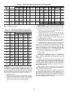
4. Check the temperature of both supply and discharge wa-
ter. Compare to Table 9. If temperature is within range,
proceed. If temperature is outside the range, check the
cooling refrigerant pressures in Table 9.
5. Check air temperature drop across the coil when com-
pressor is operating. Air temperature drop should be
between 8.3 and 13.9.
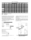
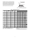
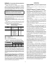
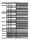
Table 8 — Water Temperature Change
Through Heat Exchanger
Unit Start-Up Heating Mode
NOTE: Operate the unit in heating cycle after checking the
cooling cycle. Allow five minutes between tests for the pres-
sure or reversing valve to equalize.
1. Turn thermostat to lowest setting and set thermostat
switch to HEAT position.
2. Slowly turn the thermostat to a higher temperature until
the compressor activates.
3. Check for warm air delivery at the unit grille within a few
minutes after the unit has begun to operate.
4. Check the temperature of both supply and discharge
water. Compare to Table 9. If temperature is within range,
proceed. If temperature is outside the range, check the
heating refrigerant pressures in Table 9.
5. Once the unit has begun to run, check for warm air deliv-
ery at the unit grille.
6. Check air temperature rise across the coil when compres-
sor is operating. Air temperature rise should be between
11.1 and 16.7 C after 15 minutes at load.
7. Check for vibration, noise and water leaks.
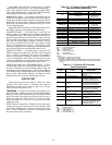
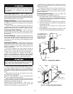
Flow Regulation — Flow regulation can be accom-
plished by two methods. Most water control valves have a flow
adjustment built into the valve. By measuring the pressure drop
through the unit heat exchanger, the flow rate can be deter-
mined. See Table 10. Adjust the water control valve until the
flow of .027 to .054 L/s per kW cooling is achieved. Since the
pressure constantly varies, two pressure gages may be needed
in some applications.
An alternative method is to install a flow control device.
These devices are typically an orifice of plastic material
designed to allow a specified flow rate that are mounted on the
outlet of the water control valve. Occasionally these valves
produce a velocity noise that can be reduced by applying some
back pressure. To accomplish this, slightly close the leaving
isolation valve of the well water setup.
WATER FLOW RATE (l/s)
COOLING
RISE (C)
HEATING
DROP (C)
Min Max Min Max
For Closed Loop: Ground
Source or Cooling/Boiler
Systems at 0.054 l/s per kW
5 6.7 2.2 4.4
For Open Loop: Ground
Water Systems 0.027 l/s per kW
11.1 14.4 5.6 9.4
To avoid possible injury or death due to electrical shock,
open the power supply disconnect switch and secure it in
an open position before flushing system.