


14
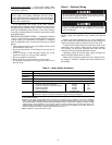
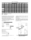
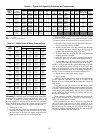
Table 3 — Electrical Data
LEGEND
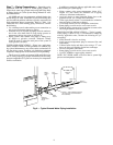
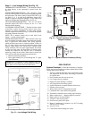
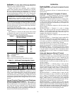
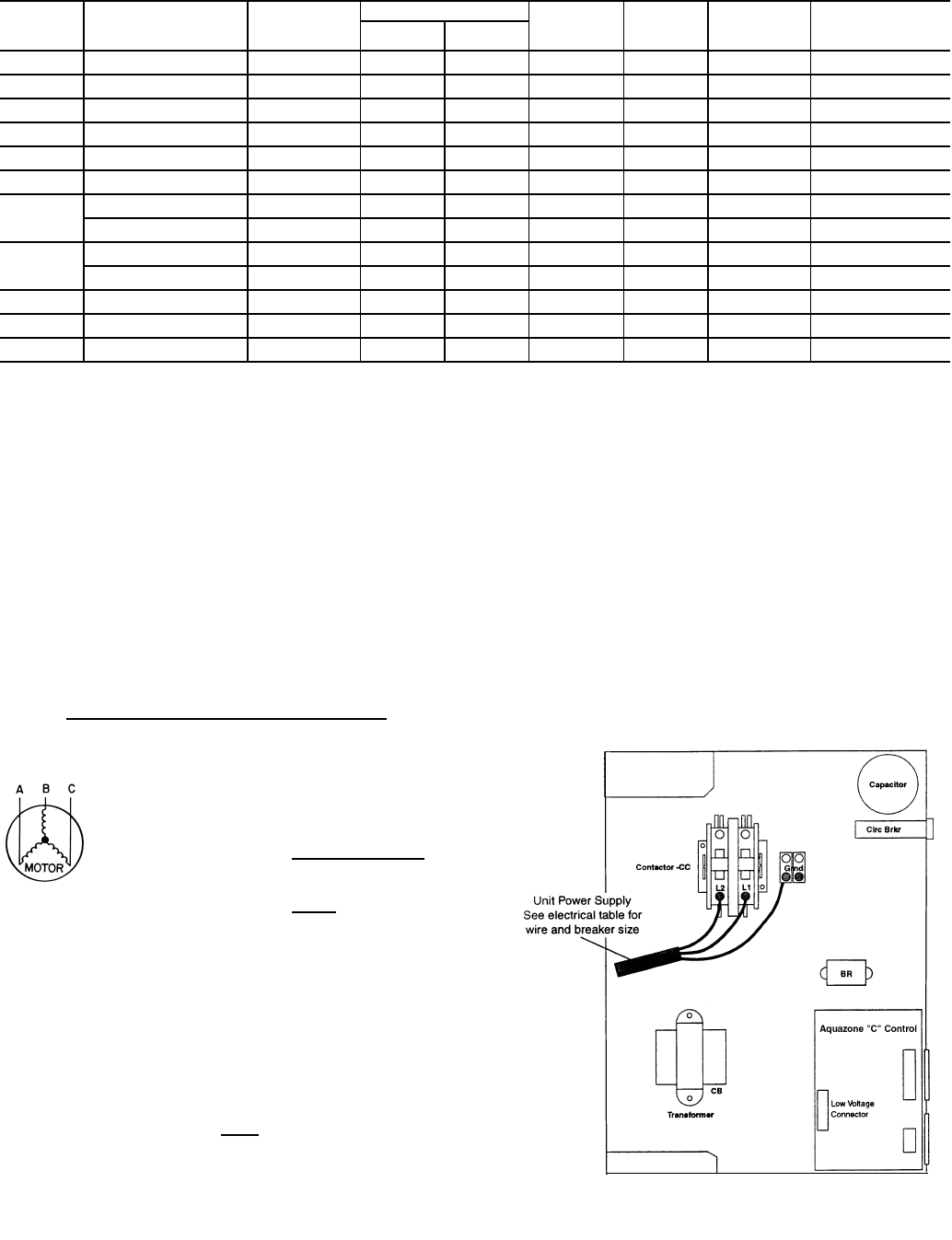
POWER CONNECTION — Make line voltage connection
by connecting the incoming line voltage wires to the L side
of the CC terminal as shown in Fig. 13. See Table 3 for
correct wire and maximum overcurrent protection sizing.
SUPPLY VOLTAGE — Operating voltage to unit must be
within voltage range indicated on unit nameplate.
On 3-phase units, voltages under load between phases must
be balanced within 2%. Use the following formula to deter-
mine the percentage voltage imbalance:
% Voltage Imbalance
Example: Supply voltage is 460-3-60.
AB = 452 volts
BC = 464 volts
AC = 455 volts
Determine maximum deviation from average voltage:
(AB) 457 – 452 = 5 v
(BC) 464 – 457 = 7 v
(AC) 457 – 455 = 2 v
Maximum deviation is 7 v.
Determine percent voltage imbalance.
= 1.53%
This amount of phase imbalance is satisfactory as it is
below the maximum allowable 2%.
Operation on improper line voltage or excessive phase
imbalance constitutes abuse and may cause damage to electri-
cal components.
NOTE: If more than 2% voltage imbalance is present, contact
local electric utility.
220-VOLT OPERATION — All 220-240 volt units are factory
wired for 208 volts. The transformers may be switched to
220-volt operation by switching the red (220 volt) wire with
the orange (240 volt) wire at the TB1-1 terminal for single-
phase and TB1-3 for 3-phase.
50RHE
UNIT
VOLTS-PHASE
(50 Hz)
VOLTAGE
MIN/MAX
COMPRESSOR FAN
MOTOR
FLA
TOTAL
UNIT
FLA
MIN
CIRCUIT
AMP
MAX
FUSE/HACR
RLA LRA
006 220/240-1 197/254 2.3 15.0 0.4 2.7 3.2 15
009 220/240-1 197/254 2.7 18.8 0.7 3.7 4.5 15
012 220/240-1 197/254 3.9 22.2 0.7 4.5 5.6 15
015 220/240-1 197/254 4.2 27.0 0.9 5.9 7.1 15
019 220/240-1 197/254 6.8 45.0 0.9 8.6 10.5 15
024 220/240-1 197/254 8.2 51.0 1.6 10.4 12.6 20
030
220/240-1 197/254 9.1 54.0 1.7 11.2 13.6 20
380-415-3 342/462 3.3 25.0 1.0 4.3 5.2 15
036
220/240-1 197/254 11.5 83.0 2.7 17.2 20.8 35
380-415-3 342/462 4.2 32.0 1.7 5.9 6.9 15
042 380-415-3 342/462 5.5 34.5 1.7 6.0 7.1 15
048 380-415-3 342/462 5.9 42.0 1.8 7.5 8.9 15
060 380-415-3 342/462 8.2 61.8 2.5 9.9 11.8 15
FLA — Full Load Amps
HACR — Heating, Air Conditioning and Refrigeration
LRA — Locked Rotor Amps
RLA — Rated Load Amps
= 100 x
max voltage deviation from average voltage
average voltage
Average Voltage =
452 + 464 + 455
3
=
1371
3
= 457
% Voltage Imbalance = 100 x
7
457
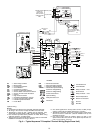
Fig. 13 — 50RHE Typical Single-Phase Line
Voltage Power Connection