


5. It is recommended that the unit base insulation around the
perimeter of the vertical return-air opening be secured to the
unit base with aluminum tape. Applicable local codes may
require aluminum tape to prevent exposed fiberglass.
6. Cover both horizontal duct openings with the duct covers from
the accessory duct cover kit. Ensure opening is air-and
watertight.
7. After completing unit conversion, perform all safety checks
and power up unit.
NOTE: The design and installation of the duct system must be in
accordance with the standards of the NFPA for installation of
nonresidence-type air conditioning and ventilating systems, NFPA
90A or residence-type, NFPA 90B; and/or local codes and
ordinances.
Adhere to the following criteria when selecting, sizing, and
installing the duct system:
8. Units are shipped for side shot installation.
9. Select and size ductwork, supply-air registers, and return-air
grilles according to American Society of Heating, Refrigera-
tion and Air Conditioning Engineers (ASHRAE) recommen-
dations.
10. Use flexible transition between rigid ductwork and unit to
prevent transmission of vibration. The transition may be
screwed or bolted to duct flanges. Use suitable gaskets to
ensure weathertight and airtight seal.
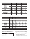
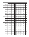
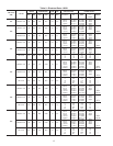
11. All units must have field-supplied filters or accessory filter
rack installed in the return-air side of the unit. Recommended
sizes for filters are shown in Tables 1 and 2.
12. Size all ductwork for maximum required airflow (either
heating or cooling) for unit being installed. Avoid abrupt duct
size increases or decreases or performance may be affected.
13. Adequately insulate and weatherproof all ductwork located
outdoors. Insulate ducts passing through unconditioned space,
and use vapor barrier in accordance with latest issue of Sheet
Metal and Air Conditioning Contractors National Association
(SMACNA) and Air Conditioning Contractors of America
(ACCA) minimum installation standards for heating and air
conditioning systems. Secure all ducts to building structure.
14. Flash, weatherproof, and vibration-isolate all openings in
building structure in accordance with local codes and good
building practices.
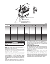
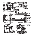
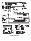
Step 8—Install Electrical Connection
The unit cabinet must have an uninterrupted, unbroken
electrical ground to minimize the possibility of personal
injury if an electrical fault should occur. This ground may
consist of an electrical wire connected to the unit ground lug
in the control compartment, or conduit approved for electrical
ground when installed in accordance with NEC (National
Electrical Code) ANSI/NFPA (latest edition) and local elec-
trical codes. In Canada, follow Canadian Electrical Code
CSA (Canadian Standards Association) C22.1 and local
electrical codes. Failure to adhere to this warning could result
in personal injury or death.
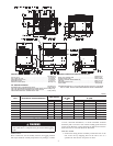
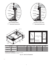
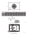
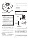
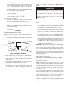
Fig. 7—Condensate Trap
C99013
1” (25mm) MIN.
2” (50mm) MIN.
TRAP
OUTLET
Table 3—Minimum Airflow for Safe Electric Heater
Operation (Cfm)
SIZE
018 024 030 036 042 048 060
700 800 1000 1200 1400 1600 2000
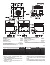
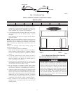
Fig. 8—Supply and Return Duct Opening
C99011
SUPPLY
DUCT
OPENING
RETURN
DUCT
OPENING
9