


Failure to follow these precautions could result in damage to
the unit being installed:
1. Make all electrical connections in accordance with NEC
ANSI/NFPA (latest edition) and local electrical codes
governing such wiring. In Canada, all electrical connec-
tions must be in accordance with CSA standard C22.1
Canadian Electrical Code Part 1 and applicable local
codes. Refer to unit wiring diagram.
2. Use only copper conductor for connections between
field-supplied electrical disconnect switch and unit. DO
NOT USE ALUMINUM WIRE.
3. Be sure that high-voltage power to unit is within operating
voltage range indicated on unit rating plate.
4. Do not damage internal components when drilling through
any panel to mount electrical hardware, conduit, etc. On
3-phase units, ensure phases are balanced within 2 percent.
Consult local power company for correction of improper
voltage and/or phase imbalance.
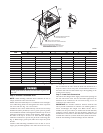
HIGH-VOLTAGE CONNECTIONS
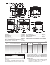
The unit must have a separate electrical service with a field-
supplied, waterproof, disconnect switch mounted at, or within
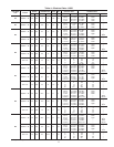
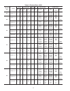
sight from, the unit. Refer to the unit rating plate for maximum
fuse/circuit breaker size and minimum circuit amps (ampacity) for
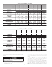
wire sizing. See Tables 4 and 5 for electrical data.
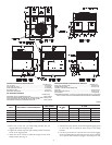
The field-supplied disconnect switch box may be mounted on the
unit over the high-voltage inlet hole when the standard power and
low-voltage entry points are used. See Fig.2&3foracceptable
location.
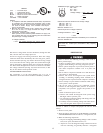
See unit wiring label and Fig. 10 for reference when making high
voltage connections. Proceed as follows to complete the high-
voltage connections to the unit.
Single phase units:
1. Run the high-voltage (L1, L2) and ground leads into the
control box.
2. Connect ground lead to chassis ground connection.
3. Connect L1 to pressure lug connection 11 of the compressor
contactor.
4. Connect L2 to pressure lug connection 23 of the compressor
contactor.
Three phase units:
1. Run the high-voltage (L1, L2, L3) and ground leads into the
control box.
2. Connect ground lead to chassis ground connection.
3. Locate the black and yellow wires connected to the lines side
of the contactor.
4. Connect field L1 to black wire on connection 11 of the
compressor contactor.
5. Connect field wire L2 to yellow wire on connection 13 of the
compressor contactor.
6. Connect field wire L3 to Blue wire from compressor.
SPECIAL PROCEDURES FOR 208-V OPERATION
Make sure that the power supply to the unit is switched OFF
and lockout tag installed before making any wiring changes.
Electrical shock can cause serious injury or death.
CONTROL VOLTAGE CONNECTIONS
NOTE: Do not use any type of power-stealing thermostat. Unit
control problems may result.
Use no. 18 American Wire Gage (AWG) color-coded, insulated
(35 C minimum) wires to make the control voltage connections
between the thermostat and the unit. If the thermostat is located
more than 100 ft. from the unit (as measured along the control
voltage wires), use no. 16 AWG color-coded, insulated (35 C
minimum) wires.
STANDARD CONNECTION
Remove knockout hole located in the electric heat panel adjacent
to the control access panel. See Fig.2&3.Remove the rubber
grommet from the installer’s packet (included with unit) and install
grommet in the knockout opening. Provide a drip loop before
running wire through panel.
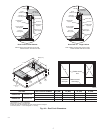
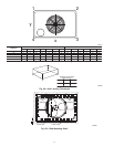
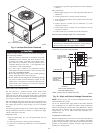
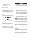
Fig. 9—Vertical Duct Cover Removed
C99012
DUCT COVERS REMOVED
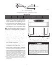
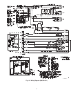
Fig. 10—High- and Control-Voltage Connections
C99010
POWER
SUPPLY
FIELD-SUPPLIED
FUSED DISCONNECT
HIGH VOLTAGE
POWER LEADS
(SEE UNIT WIRING
LABEL)
GND
CONTROL BOX
SPLICE BOX
LOW-VOLTAGE
POWER LEADS
(SEE UNIT
WIRING LABEL)
Y
G
R
C
YEL(Y)
GRN(G)
RED(R)
BRN(C)
THERMOSTAT
(TYPICAL)
LEGEND
Field Control-Voltage Wiring
Field High-Voltage Wiring
NOTE: Use blue wire for 3-phase units only.
10