


CONDENSER COIL, EVAPORATOR COIL, AND CONDEN-
SATE DRAIN PAN
Inspect the condenser coil, evaporator coil, and condensate drain
pan at least once each year.
The coils are easily cleaned when dry; therefore, inspect and clean
the coils either before or after each cooling season. Remove all
obstructions, including weeds and shrubs, that interfere with the
airflow through the condenser coil.
Straighten bent fins with a fin comb. If coated with dirt or lint,
clean the coils with a vacuum cleaner, using the soft brush
attachment. Be careful not to bend the fins. If coated with oil or
grease, clean the coils with a mild detergent-and-water solution.
Rinse coils with clear water, using a garden hose. Be careful not to
splash water on motors, insulation, wiring, or air filter(s). For best
results, spray condenser coil fins from inside to outside the unit.
On units with an outer and inner condenser coil, be sure to clean
between the coils. Be sure to flush all dirt and debris from the unit
base.
Inspect the drain pan and condensate drain line when inspecting
the coils. Clean the drain pan and condensate drain by removing all
foreign matter from the pan. Flush the pan and drain tube with
clear water. Do not splash water on the insulation, motor, wiring,
or air filter(s). If the drain tube is restricted, clear it with a
“plumbers snake” or similar probe device. Ensure that the auxiliary
drain port above the drain tube is also clear
CONDENSER FAN
Keep the condenser fan free from all obstructions to ensure
proper cooling operation. Never place articles on top of the
unit. Damage to unit may result.
1. Remove 6 screws holding condenser grille and motor to top
cover.
2. Turn motor/grille assembly upside down on top cover to
expose the fan blade.
3. Inspect the fan blades for cracks or bends.
4. If fan needs to be removed, loosen the setscrew and slide the
fan off the motor shaft.
5. When replacing fan blade, position blade so that the hub is 1/8
in. away from the motor end (1/8 in. of motor shaft will be
visible).
6. Ensure that setscrew engages the flat area on the motor shaft
when tightening
7. Replace grille.
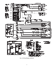
ELECTRICAL CONTROLS AND WIRING
Inspect and check the electrical controls and wiring annually. Be
sure to turn off the electrical power to the unit and install lockout
tag.
Remove access panel to locate all the electrical controls and
wiring. Check all electrical connections for tightness. Tighten all
screw connections. If any smoky or burned connections are
noticed, disassemble the connection, clean all the parts, restrip the
wire end and reassemble the connection properly and securely.
After inspecting the electrical controls and wiring, replace the
access panel. Start the unit, and observe at least one complete
heating cycle and one complete cooling cycle to ensure proper
operation. If discrepancies are observed in either or both operating
cycles, or if a suspected malfunction has occurred, check each
electrical component with the proper electrical instrumentation.
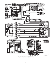
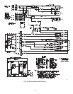
Refer to the unit wiring label when making these checkouts.
NOTE: Refer to the heating and/or cooling sequence of operation
in this publication as an aid in determining proper control
operation
REFRIGERANT CIRCUIT
Inspect all refrigerant tubing connections and the unit base for oil
accumulations annually. Detecting oil generally indicates a refrig-
erant leak.
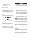
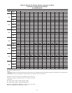
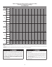
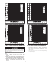
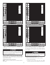
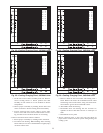
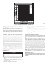
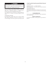
Fig. 27—Cooling Charging Chart, 50GX060 Units
C99049
°
OUTDOOR TEMP
° F ° C
115 46
45 7
55 13
65 18
75 24
95 35
105 41
85 29
(060) 60HZ CHARGING CHART
24