


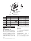
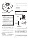

2. Place each of the four (4) metal lifting brackets into the
rigging holds in the composite pan.
3. Tighten the ratchet strap unit tight. Lifting brackets should be
secure in the rigging holds.
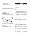
4. Attach the clevis or hook of sufficient strength to hole in the
lifting bracket (See Fig. 6).
5. Attach safety straps directly to the field supplied rigging straps
or clevis clip. Do not attach the safety straps to the lifting
brackets.
6. Use the top of the unit as a spreader bar to prevent the rigging
straps from damaging the unit. If the wood top is not available,
use a spreader bar of sufficient length to not damage the unit.
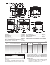
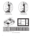
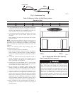
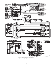
Fig. 3— 50GS048–060 and 50GX042–060 Unit Dimensions
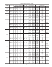
UNIT ELECTRICAL CHARACTERISTICS
UNIT WEIGHT
UNIT HEIGHT
IN. (MM)
”A”
CENTER OF GRAVITY
IN. (MM)
lb. kg X Y Z
50GS048 208/230-1-60, 208/230-3-60, 460-3-60 324 145 38.98 (990.2) 20.0 (508.0) 17.0 (432.0) 17.0 (432.0)
50GS060 208/230-1-60, 208/230-3-60, 460-3-60 389 176 38.98 (990.2) 19.0 (482.6) 16.0 (406.0) 17.0 (432.0)
50GX042 208/230-1-60, 208/230-3-60, 460-3-60 321 146 38.98 (990.2) 20.5 (520.7) 16.75 (425.5) 16.6 (421.6)
50GX048 208/230-1-60, 208/230-3-60, 460-3-60 326 148 38.98 (990.2) 19.5 (495.3) 17.6 (447.6) 18.0 (457.2)
50GX060 208/230-1-60, 208/230-3-60, 460-3-60 399 181 42.98 (1091.1) 20.5 (520.7) 16.2 (412.8) 17.6 (447.0)
C99006
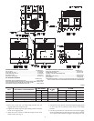
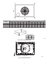
REQUIRED CLEARANCE FOR OPERATION AND SERVICING
INCHES [mm]
EVAP. COIL ACCESS SIDE............................................................36.00 [914.0]
POWER ENTRY SIDE....................................................................36.00 [914.0]
(EXCEPT FOR NEC REQUIREMENTS)
UNIT TOP.......................................................................................48.00 [1219.2]
SIDE OPPOSITE DUCTS ..............................................................36.00 [914.0]
DUCT PANEL.................................................................................12.00 [304.8] *
*MINIMUM DISTANCES: IF UNIT IS PLACED LESS THAN 304.8 [12.00] FROM
WALL SYSTEM, THEN SYSTEM PERFORMANCE MAYBE COMPROMISE.
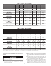
REQUIRED CLEARANCE TO COMBUSTIBLE MATL.
INCHES [mm]
TOP OF UNIT...................................................................................14.00 [355.6]
DUCT SIDE OF UNIT.........................................................................2.00 [50.8]
SIDE OPPOSITE DUCTS ................................................................14.00 [355.6]
BOTTOM OF UNIT.............................................................................0.50 [12.7]
ELECTRIC HEAT PANEL.................................................................36.00 [914.4]
NEC. REQUIRED CLEARANCES.
INCHES [mm]
BETWEEN UNITS, POWER ENTRY SIDE....................................42.00 [1066.8]
UNIT AND UNGROUNDED SURFACES, POWER ENTRY SIDE .36.00 [914.0]
UNIT AND BLOCK OR CONCRETE WALLS AND OTHER
GROUNDED SURFACES, POWER ENTRY SIDE.........................42.00 [1066.8]
4