


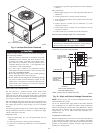

Accessory lifting kit is only to be used with Small Packaged
units which have a composite base pan with molded rigging
holds.
INSPECTION
Prior to initial use, and at monthly intervals, all rigging brackets
and straps should be visually inspected for any damage, evidence
of wear, structural deformation, or cracks. Particular attention
should be paid to excessive wear at hoist hooking points and load
support areas. Brackets or straps showing any kind of wear in these
areas must not be used and should be discarded.
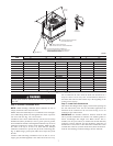
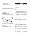
INSTALLATION
1. Position the lifting bracket assembly around the base of the
unit. Leave the top shipping skid on the unit to act as a
spreader bar. Be sure the strap does not twist.
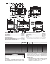
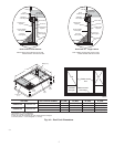
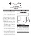
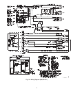
Fig. 2— 50GS018-042 and 50GX024-036 Unit Dimensions
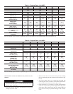
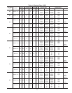
UNIT ELECTRICAL CHARACTERISTICS
UNIT WEIGHT
UNIT HEIGHT
IN. (MM)
”A”
CENTER OF GRAVITY
IN. (MM)
lb. kg X Y Z
50GS018 208/230-1-60 254 115.2 35.02 (889.5) 20.0 (508.0) 13.0 (330.2) 15.0 (381.0)
50GS024 208/230-1-60 260 117.9 35.02 (889.5) 19.0 (482.6) 13.0 (330.2) 15.0 (381.0)
50GS030 208/230-1-60, 208/230-3-60 258 117.0 35.02 (889.5) 19.0 (482.6) 14.0 (355.6) 15.0 (381.0)
50GS036 208/230-1-60, 208/230-3-60, 460-3-60 268 121.6 37.02 (940.3) 20.0 (508.0) 14.0 (355.6) 13.0 (330.2)
50GS042 208/230-1-60, 208/230-3-60, 460-3-60 294 133.3 35.02 (889.5) 19.0 (482.6) 14.0 (355.6) 13.0 (330.2)
50GX024 208/230-1-60 270 122.5 37.02 (940.3) 18.5 (469.9) 14.5 (368.3) 16.0 (406.4)
50GX030 208/230-1-60, 208/230-3-60 291 132.0 39.02 (991.1) 19.5 (495.3) 15.5 (393.7) 17.6 (447.0)
50GX036 208/230-1-60, 208/230-3-60, 460-3-60 299 135.6 35.02 (889.5) 19.5 (495.3) 15.25 (387.4) 16.5 (419.1)
C99007
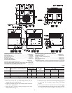
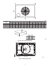
REQUIRED CLEARANCE FOR OPERATION AND SERVICING
INCHES [mm]
EVAP. COIL ACCESS SIDE............................................................36.00 [914.0]
POWER ENTRY SIDE....................................................................42.00 [1066.8]
(EXCEPT FOR NEC REQUIREMENTS)
UNIT TOP.......................................................................................48.00 [1219.2]
SIDE OPPOSITE DUCTS..............................................................36.00 [914.0]
DUCT PANEL.................................................................................12.00 [304.8] *
*MINIMUM DISTANCES: IF UNIT IS PLACED LESS THAN 304.8 [12.00] FROM
WALL SYSTEM, THEN SYSTEM PERFORMANCE MAYBE COMPROMISE.
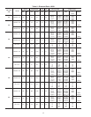
REQUIRED CLEARANCE TO COMBUSTIBLE MATL.
INCHES [mm]
TOP OF UNIT...................................................................................14.00 [355.6]
DUCT SIDE OF UNIT.........................................................................2.00 [50.8]
SIDE OPPOSITE DUCTS................................................................14.00 [355.6]
BOTTOM OF UNIT.............................................................................0.50 [12.7]
ELECTRIC HEAT PANEL.................................................................36.00 [914.4]
NEC. REQUIRED CLEARANCES.
INCHES [mm]
BETWEEN UNITS, POWER ENTRY SIDE....................................42.00 [1066.8]
UNIT AND UNGROUNDED SURFACES, POWER ENTRY SIDE .36.00 [914.0]
UNIT AND BLOCK OR CONCRETE WALLS AND OTHER
GROUNDED SURFACES, POWER ENTRY SIDE.........................42.00 [1066.8]
3