


leak. Leak test all refrigerant tubing connections using
electronic leak detector, halide torch, or liquid-soap solu-
tion. If a refrigerant leak is detected, see Check for
Refrigerant Leaks section.
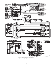
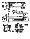
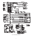
c. Inspect all field- and factory-wiring connections. Be sure
that connections are completed and tight.
d. Ensure electrical wiring does not contact refrigerant tubes
or sharp metal edges.
e. Inspect coil fins. If damaged during shipping and handling,
carefully straighten fins with a fin comb.
Verify the following conditions:
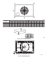
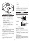
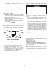
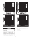
a. Make sure that condenser-fan blade is correctly positioned
in fan orifice. Leading edge of condenser-fan blade should
be 1/2 in. maximum from fan orifice (See Fig. 11).
b. Make sure that air filter(s) is in place.
c. Make sure that condensate drain trap is filled with water to
ensure proper drainage.
d. Make sure that all tools and miscellaneous loose parts have
been removed.
START-UP
CHECK FOR REFRIGERANT LEAKS
Proceed as follows to locate and repair a refrigerant leak and to
charge the unit:
1. Locate leak and make sure that refrigerant system pressure has
been relieved and reclaimed from both high- and low-pressure
ports.
2. Repair leak following accepted practices. NOTE: Install a
filter drier whenever the system has been opened for repair.
3. Add a small charge of R-22 refrigerant vapor to system and
leak-test unit.
4. Recover refrigerant from refrigerant system and evacuate to
500 microns if no additional leaks are not found.
5. Charge unit with R-22 refrigerant, using a volumetric-
charging cylinder or accurate scale. Refer to unit rating plate
for required charge. Be sure to add extra refrigerant to
compensate for internal volume of filter drier.
START UP COOLING SECTION AND MAKE ADJUST-
MENTS
Complete the required procedures given in the Pre-Start- Up
section before starting the unit. Do not jumper any safety
devices when operating the unit. Do not operate the compres-
sor when the outdoor temperature is below 40°F (unless
accessory low-ambient kit is installed). Do not rapid-cycle the
compressor. Allow 5 minutes between “on” cycles to prevent
compressor damage.
CHECKING COOLING CONTROL OPERATION
Start and check the unit for proper cooling control operation as
follows:
1. Place room thermostat SYSTEM switch in OFF position.
Observe that blower motor starts when FAN switch is placed
in ON position and shuts down after 30 second fan time delay
expires when FAN switch is placed in AUTO position.
2. Place SYSTEM switch in COOL position and FAN switch in
AUTO position. Set cooling control below room temperature.
Observe that compressor, condenser fan, and evaporator
blower motors start. Observe that compressor and outdoor fan
shut down when control setting is satisfied and that indoor
blower shuts down after 30 second fan time delay expires.
3. When using an auto-changeover room thermostat, place both
SYSTEM and FAN switches in AUTO positions. Observe that
unit operates in heating mode when temperature control is set
to “call for heating” (above room temperature) and operates in
cooling mode when temperature control is set to “call for
cooling” (below room temperature).
IMPORTANT: Three-phase, scroll compressor units (50GS048,
50GX030-060) are direction-oriented. These units must be
checked to ensure proper compressor 3-phase power lead orienta-
tion. If not corrected within 5 minutes, the internal protector will
shut off the compressor. The 3-phase power leads to the unit must
be reversed to correct rotation. When turning backwards, scroll
compressors emit elevated noise levels, and the difference between
compressor suction and
discharge pressures may be
dramatically lower than normal.
CHECKING AND ADJUSTING REFRIGERANT CHARGE
The refrigerant system is fully charged with R-22 refrigerant,
tested, and factory-sealed.
NOTE: Adjustment of the refrigerant charge is not required
unless the unit is suspected of not having the proper R-22 charge.
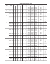
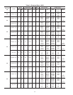
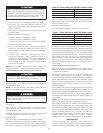
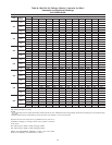
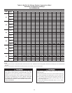
A superheat charging chart is attached to the outside of the service
access panel. The chart includes the required suction line tempera-
ture at given suction line pressures and outdoor ambient tempera-
tures (See Fig. 15–27).
An accurate superheat, thermocouple- or thermistor-type ther-
mometer, a sling psychrometer, and a gauge manifold are required
when using the superheat charging method for evaluating the unit
charge. Do not use mercury or small dial-type thermometers
because they are not adequate for this type of measurement.
NOTE: Allow system to operate in the cooling mode for a
minimum of 10 minutes before checking or adjusting refrigerant
charge.
Fig. 11—Fan Blade Clearance
C99009
FAN GRILLE
MOTOR
1/8" MAX BETWEEN
MOTORAND FAN HUB
MOTOR SHAFT
1/2˝
14