


When evaluating the refrigerant charge, an indicated adjust-
ment to the specified factory charge must always be very
minimal. If a substantial adjustment is indicated, an abnormal
condition exists somewhere in the cooling system, such as
insufficient airflow across either coil or both coils.
Proceed as follows:
1. Remove caps from low- and high-pressure service fittings.
2. Using hoses with valve core depressors, attach low- and
high-pressure gauge hoses to low- and high-pressure service
fittings, respectively.
3. Start unit in Cooling mode and let unit run until system
pressures stabilize.
4. Measure and record the following:
a. Outdoor ambient-air temperature (°F db).
b. Evaporator inlet-air temperature (°F wb).
c. Suction-tube temperature (°F) at low-side service fitting.
d. Suction (low-side) pressure (psig).
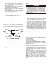
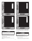
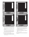
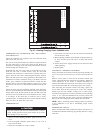
5. Using “Cooling Charging Charts” compare outdoor-air tem-
perature (°F db) with the suction line pressure (psig) to
determine desired system operating suction line temperature.
See Fig. 15-27.
6. Compare actual suction-tube temperature with desired
suction-tube temperature. Using a tolerance of ±3°F, add
refrigerant if actual temperature is more than 3°F higher than
proper suction-tube temperature, or remove refrigerant if
actual temperature is more than 3°F lower than required
suction-tube temperature.
NOTE: If the problem causing the inaccurate readings is a
refrigerant leak, refer to Check for Refrigerant Leaks section.
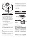
INDOOR AIRFLOW AND AIRFLOW ADJUSTMENTS
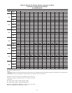
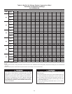
For cooling operation, the recommended airflow is 350 to 450
cfm for each 12,000 Btuh of rated cooling capacity.
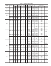
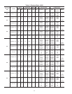
Tables 8 and 9 show cooling airflows at various external static
pressures. Refer to these tables to determine the airflow for the
system being installed.
NOTE: Be sure that all supply- and return-air grilles are open,
free from obstructions, and adjusted properly.
Disconnect electrical power to the unit and install lockout tag
before changing blower speed. Electrical shock can cause
serious injury or death.
Airflow can be changed by changing the lead connections of the
blower motor.
Unit 50GS two- or three-speed motors (except size 030) are
factory wired for low speed operation. Unit 50GS030 is factory
wired for medium speed.
All 50GX units are factory wired for low speed and may need to
be wired for medium or high speed in the field.
FOR 208/230V
For color coding on the 208/230V motor leads, see Table 6.
To change the speed of the indoor fan motor (IFM), remove the fan
motor speed leg lead from the time delay relay (TDR). This wire
is attached to terminal–3 of TDR for single-phase and 3-phase
units. To change the speed, remove and replace with lead for
desired blower motor speed. Insulate the removed lead to avoid
contact with chassis parts.
FOR 460-V GE MOTORS
For color coding on the 460-v GE motor leads, see Table 7.
To change the speed of the indoor fan motor (IFM), remove fan
motor speed lead from the time delay relay (TDR) and replace with
the lead for the desired blower motor speed. The motor speed lead
is attached to terminal–3 of TDR. For low and medium speeds
black must be connected to the jumper wire. Insulate removed lead
end to avoid contact with chassis parts. To select high speed on
460-v GE motors, separate the black female quick connect (QC)
from the jumper lead male quick connect (QC) and connect the
black lead to the BR. Insulate the jumper to avoid contact with any
chassis parts.
COOLING SEQUENCE OF OPERATION
With the room thermostat SYSTEM switch in the COOL position
and the FAN switch in the AUTO position, the cooling sequence
of operation is as follows:
When the room temperature rises to a point that is slightly above
the cooling control setting of the thermostat, the thermostat
completes the circuit between thermostat terminal R to terminals Y
and G. These completed circuits through the thermostat connect
contactor coil (C) (through unit wire Y) and time delay relay
(TDR) (through unit wire G) across the 24-v secondary of
transformer (TRAN).
The normally open contacts of energized contactor (C) close and
complete the circuit through compressor motor (COMP) to con-
denser (outdoor) fan motor (OFM). Both motors start instantly.
The set of normally open contacts of energized relay TDR close
and complete the circuit through evaporator blower (indoor) fan
motor (IFM).
NOTE: Once the compressor has started and then has stopped, it
should not be started again until 5 minutes have elapsed.
The cooling cycle remains “on” until the room temperature drops
to a point that is slightly below the cooling control setting of the
room thermostat. At this point, the thermostat “breaks” the circuit
between thermostat terminal R to terminals Y and G. These open
circuits deenergize contactor coil C and relay coil TDR. The
condenser and compressor motors stop. After a 30-second delay,
the blower motor stops. The unit is in a “standby” condition,
waiting for the next “call for cooling” from the room thermostat.
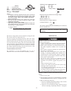
MAINTENANCE
To ensure continuing high performance, and to minimize the
possibility of premature equipment failure, periodic maintenance
must be performed on this equipment. This cooling unit should be
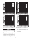
Table 6—Color Coding for 208/230–V Motor Leads
3-SPEED 2-SPEED
black = high speed black = high speed
blue = medium speed -
red = low speed red = low speed
Table 7—Color Coding for 460-V GE Motor Leads
3-SPEED 2-SPEED
black = high black = high
violet = jumper blue = jumper
orange = medium -
red = low red = low
18