


Lifting point should be directly over the center of gravity for
the unit.
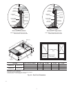
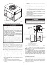
Step 6—Connect Condensate Drain
NOTE: When installing condensate drain connection be sure to
comply with local codes and restrictions.
Models 50GS and 50GX dispose of condensate water through a
3/4 in. NPT fitting which exits through the base on the evaporator
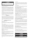
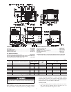
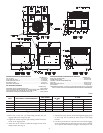
coil access side. See Fig.2&3forlocation.
Condensate water can be drained directly onto the roof in rooftop
installations (where permitted) or onto a gravel apron in ground-
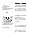
level installations. Install a field-supplied condensate trap at end of
condensate connection to ensure proper drainage. Make sure that
the outlet of the trap is at least 1 in. lower than the drainpan
condensate connection to prevent the pan from overflowing (See
Fig. 7). When using a gravel apron, make sure it slopes away from
the unit.
Connect a drain tube using a minimum of 3/4 -in. PVC or 3/4 -in.
copper pipe (all field-supplied) at the outlet end of the 2-in. trap.
Do not undersize the tube. Pitch the drain tube downward at a
slope of at least 1-in. for every 10 ft. of horizontal run. Be sure to
check the drain tube for leaks. Prime trap at the beginning of the
cooling season start-up.
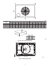
Step 7—Install Duct Connections
The unit has duct flanges on the supply- and return-air openings on
the side and bottom of the unit. For downshot applications the
ductwork can be connected to the roof curb. See Fig.2&3for
connection sizes and locations.
IMPORTANT: Use flexible connectors between ductwork and
unit to prevent transmission of vibration. Use suitable gaskets to
ensure weathertight and airtight seal. When electric heat is
installed, use fire proof canvas (or similar heat resistant material)
connector between ductwork and unit discharge connection. If
flexible duct is used, insert a sheet metal sleeve inside duct. Heat
resistant duct connector (or sheet metal sleeve) must extend 24-in.
from the unit discharge connection flange into the ductwork.
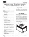
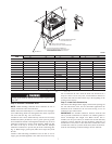
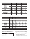
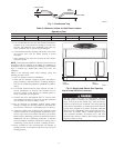
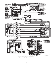
Fig. 6—Suggested Rigging
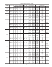
SIZE
MAXIMUM WEIGHT A B
lb. kg in. mm. in. mm.
UNIT 50GS
018 276 125.2 20 508.0 13 330.2
024 282 127.9 19 482.6 13 330.2
030 280 127.0 19 482.6 14 355.6
036 290 131.5 20 508.0 14 355.6
042 316 143.3 19 482.6 14 355.6
048 346 156.9 20 508 17 431.8
060 411 186.4 19 482.6 16 406.4
UNIT 50GX
024 292 132.5 18.5 469.9 14.50 368.3
030 313 142.5 19.5 495.3 15.50 393.7
036 321 145.6 19.5 495.3 15.25 387.4
042 343 155.6 20.5 520.7 16.75 425.5
048 348 157.9 19.5 495.3 17.62 447.6
060 421 191.0 20.5 520.7 16.25 412.8
C99066
PLACE RIGGING BRACKET ASSEMBLY IN 4
RIGGING HOLES AND INSTALL TIE DOWN STRAP
AROUND PERIMETER OF UNIT AND THROUGH
SPACE IN BRACKET ASSEMBLY
INSTALL SAFETY STRAPS TO
RIGGING CLEVIS AT 4 RIGGING BRACKETS
TIGHTEN STRAPPING SECURELY
WITH TENSION BUCKLE
SEE DETAIL A
DETAIL A
SCALE 0.250
914-137"
(36"-54")
“A”
“B”
7