


Before performing service or maintenance operations on
system, turn off power to unit. Turn off accessory heater
power switch, if applicable. Electrical shock can cause
personal injury.
Recognize safety information. This is the safety-alert symbol .
When you see this symbol in instructions or manuals, be alert to
the potential for personal injury.
Understand the signal words DANGER, WARNING, CAUTION,
and NOTE. These words are used with the safety-alert symbol.
DANGER identifies the most serious hazards which will result in
severe personal injury or death. WARNING signifies a hazard
which could result in personal injury or death. CAUTION is used
to identify unsafe practices which would result in minor personal
injury or product and property damage. NOTE is used to highlight
suggestions which will result in enhanced installation, reliability,
or operation.
These instructions cover minimum requirements and conform to
existing national standards and safety codes. In some instances,
these instructions exceed certain local codes and ordinances,
especially those that may not have kept up with changing residen-
tial construction practices. We require these instructions as a
minimum for a safe installation.
INTRODUCTION
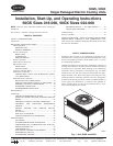
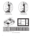
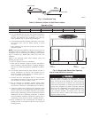
The 50GS and 50GX units (see Fig. 1) are fully self-contained, and
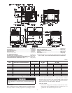
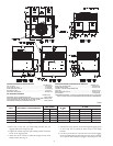
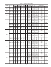
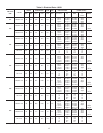
designed for outdoor installation. See Figs. 2 and 3 for unit
dimensions. All unit sizes have discharge openings for both
horizontal and downflow configurations, and are factory shipped
with all downflow duct openings covered . Units may be installed
either on a rooftop, ground-level cement slab, or directly on the
ground if local codes permit. (See Fig. 4A for roof curb dimen-
sions.)
RECEIVING AND INSTALLATION
Step 1—Check Equipment
IDENTIFY UNIT
The unit model number and serial number are stamped on the unit
identification plate. Check this information against shipping pa-
pers.
INSPECT SHIPMENT
Inspect for shipping damage while unit is still on shipping pallet.
If unit appears to be damaged or is torn loose from its anchorage,
have it examined by transportation inspectors before removal.
Forward claim papers directly to transportation company. Manu-
facturer is not responsible for any damage incurred in transit.
Check all items against shipping list. Immediately notify the
nearest Carrier Air Conditioning office if any item is missing. To
prevent loss or damage, leave all parts in original packages until
installation.
Step 2—Provide Unit Support
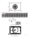
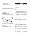
ROOF CURB
Install accessory roof curb in accordance with instructions shipped
with curb (See Fig. 4A). Install insulation, cant strips, roofing, and
flashing. Ductwork must be attached to curb.
IMPORTANT: The gasketing of the unit to the roof curb is critical
for a watertight seal. Install gasketing material supplied with the
roof curb. Improperly applied gasketing also can result in air leaks
and poor unit performance.
Curb should be level to within 1/4 in. (See Fig. 5A). This is
necessary for unit drain to function properly. Refer to accessory
roof curb installation instructions for additional information as
required.
SLAB MOUNT
Place the unit on a solid, level concrete pad that is a minimum of
4 in. thick with 2 in. above grade (See Fig. 5B). The slab should
extend approximately 2 in. beyond the casing on all 4 sides of the
unit. Do not secure the unit to the slab except when required by
local codes.
GROUND MOUNT
The unit may be installed either on a slab or placed directly on the
ground if local codes permit. Place the unit on level ground
prepared with gravel for condensate discharge.
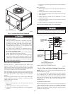
Step 3—Provide Clearances
The required minimum service clearances are shown in Fig.2&3.
Adequate ventilation and outdoor air must be provided. The
outdoor fan draws air through the outdoor coil and discharges it
through the top fan grille. Be sure that the fan discharge does not
recirculate to the outdoor coil. Do not locate the unit in either a
corner or under an overhead obstruction. The minimum clearance
under a partial overhang (such as a normal house overhang) is 36
in. above the unit top. The maximum horizontal extension of a
partial overhang must not exceed 48 in. For extended overhangs,
provide a minimum clearance of 48 in.
IMPORTANT: Do not restrict outdoor airflow. An air restriction
at either the outdoor-air inlet or the fan discharge may be
detrimental to compressor life.
Do not place the unit where water, ice, or snow from an overhang
or roof will damage or flood the unit. Do not install the unit on
carpeting or other combustible materials. Slab-mounted units
should be at least 4 in. above the highest expected water and runoff
levels. Do not use unit if it has been under water.
Step 4—Field Fabricate Ductwork
Secure all ducts to roof curb and building structure on vertical
discharge units. Do not connect ductwork to unit. For horizontal
applications, unit is provided with flanges on the horizontal
openings. All ductwork should be secured to the flanges. Insulate
and weatherproof all external ductwork, joints, and roof openings
with counter flashing and mastic in accordance with applicable
codes.
Ducts passing through an unconditioned space must be insulated
and covered with a vapor barrier. If a plenum return is used on a
vertical unit, the return should be ducted through the roof deck to
comply with applicable fire codes. A minimum clearance is not
required around ductwork. Cabinet return-air static shall not
exceed -.25 in. wg.
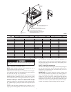
Step 5—Rig and Place Unit
Rigging and handling of this equipment can be hazardous for many
reasons due to the installation location (roofs, elevated structures,
etc.)
Only trained, qualified crane operators and ground support staff
should handle and install this equipment.
When working with this equipment, observe precautions in the
literature, on tags, stickers, and labels attached to the equipment,
and any other safety precautions that might apply.
Follow all applicable safety codes. Wear safety shoes and work
gloves.
Never stand beneath rigged units or lift over people.
Never exceed 200 lbs. per bracket lifting force.
2