


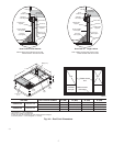

CONFIGURING UNITS FOR DOWNFLOW (VERTICAL) DIS-
CHARGE
Before performing service or maintenance operations on the
system, turn off main power to unit and install lockout tag or
electrical shock could result.
1. Open all electrical disconnects and install lockout tag before
starting any service work.
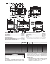
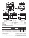
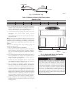
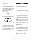
2. Remove return duct cover located on duct panel by breaking
four (4) connecting tabs with screwdriver and a hammer. (Fig.
8&9)
3. To remove supply duct cover, break front and right side
connecting tabs with a screwdriver and a hammer. Push louver
down to break rear and left side tabs. (Fig.8&9)
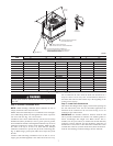
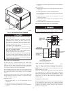
4. If unit ductwork is to be attached to vertical opening flanges
on the unit composite base (jackstand applications only), do so
at this time. Collect ALL screws that were removed. Do not
leave screws on rooftop as permanent damage to the roof may
occur.
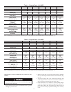
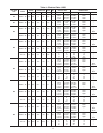
Table 1—Physical Data—Unit 50GS
UNIT SIZE 018 024 030 036 042 048 060
NOMINAL CAPACITY (ton) 1-1/2 2 2-1/2 3 3-1/2 4 5
OPERATING WEIGHT (lb.) 254 260 258 268 294 324 389
COMPRESSOR Reciprocating Scroll Reciprocating
REFRIGERANT (R-22)
Quantity (lb.)
2.6 3.5 3.65 4.4 6.4 5.1 7.4
REFRIGERANT METERING DEVICE
Orifice ID (in.)
Accurater
.034 .034 .034 .032 .034 .032 .030
CONDENSER COIL
Rows...Fins/in.
Face Area (sq. ft.)
1...17
6.1
1...17
9.1
1...17
9.1
1...17
10.9
1...17
9.1
1...17
12.3
2...17
12.3
CONDENSER FAN
Nominal Cfm
Diameter
Motor Hp (Rpm)
2000
22
1/8 (825)
2400
22
1/8 (825)
2400
22
1/8 (825)
3000
18
1/4 (1100)
3000
22
1/4 (1100)
3600
22
1/4 (1100)
3600
22
1/4 (1100)
EVAPORATOR COIL
Rows...Fins/in.
Face Area (sq. ft.)
2...15
3.1
2...15
3.1
2...15
3.7
3...15
3.06
4...15
3.06
3...15
4.7
4...15
4.7
EVAPORATOR BLOWER
Nominal Airflow (Cfm)
Size (in.)
Motor HP (RPM)
600
10x10
1/4 (825)
800
10x10
1/4 (1075)
1000
10x10
1/4 (1075)
1200
11x10
1/2 (1075)
1400
11x10
3/4 (1075)
1600
11x10
3/4 (1075)
2000
11x10
1.0 (1100)
RETURN-AIR FILTERS (in.)*
Throwaway
20x20 20x20 20x20 20x24 20x24 24x30 24x30
* Required filter sizes shown are based on the larger of the ARI (Air Conditioning and Refrigeration Institute) rated cooling airflow or the heating airflow velocity of 300
ft./min. for throwaway type or 450 ft./min. for high-capacity type. Air filter pressure drop for non-standard filters must not exceed 0.08 in. wg.
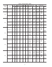
Table 2—Physical Data—Unit 50GX
UNIT SIZE 024 030 036 042 048 060
NOMINAL CAPACITY (ton) 2 2-1/2 3 3-1/2 4 5
OPERATING WEIGHT (lb.) 270 291 299 321 326 399
COMPRESSOR Scroll
REFRIGERANT (R-22)
Quantity (lb.)
3.7 4.4 5.2 7.6 8.3 8.1
REFRIGERANT METERING DEVICE
Orifice ID (in.)
Accurater
.034 .030 .032 .034 .034 .032
CONDENSER COIL
Rows...Fins/in.
Face Area (sq. ft.)
1...17
10.8
1...17
12.7
2...17
9.1
2...17
9.1
2...17
12.3
2...17
16.4
CONDENSER FAN
Nominal Cfm
Diameter (in.)
Motor Hp (Rpm)
2350
22
1/8 (825)
2350
22
1/8 (825)
2350
22
1/8 (825)
3300
22
1/4 (1100)
3300
22
1/4 (1100)
3300
22
1/4 (1100)
EVAPORATOR COIL
Rows...Fins/in.
Face Area (sq. ft.)
3...15
3.1
3...15
3.1
3...15
3.7
3...15
4.7
4...15
4.7
4...15
4.7
EVAPORATOR BLOWER
Nominal Airflow (Cfm)
Size (in.)
Motor Hp (RPM)
800
10x10
1/4 (1075)
1000
10x10
1/4 (1075)
1200
11x10
1/2 (1075)
1400
11x10
3/4 (1075)
1600
11x10
3/4 (1075)
1750
11x10
1.0 (1040)
RETURN-AIR FILTERS (in.)*
Throwaway
20x20 20x20 20x24 20x30 24x30 24x30
*
Required filter sizes shown are based on the larger of the ARI (Air Conditioning and Refrigeration Institute) rated cooling airflow or the heating airflow velocity of 300
ft./min. for throwaway type or 450 ft./min. for high-capacity type. Air filter pressure drop for non-standard filters must not exceed 0.08 in. wg.
8