


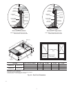
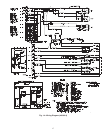

Run the low-voltage leads from the thermostat, through the inlet
hole, and into unit low-voltage splice box.
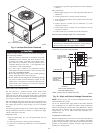
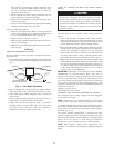
Locate five 18-gage wires leaving control box. These low-voltage
connection leads can be identified by the colors red, green, yellow,
brown, and white (See Fig. 10). Ensure the leads are long enough
to be routed into the low-voltage splice box (located below right
side of control box). Stripped yellow wire is located in connection
box. Route leads through hole in bottom of control box and make
low-voltage connections (See Fig. 10). Secure all cut wires, so that
they do not interfere with operation of unit.
TRANSFORMER PROTECTION
The transformer is of the energy-limiting type. It is set to
withstand a 30-second overload or shorted secondary condition.
PRE-START-UP
Failure to observe the following warnings could result in
serious personal injury:
1. Follow recognized safety practices and wear protective
goggles when checking or servicing refrigerant system.
2. Do not operate compressor or provide any electric power to
unit unless compressor terminal cover is in place and
secured.
3. Do not remove compressor terminal cover until all electri-
cal sources are disconnected.
4. Relieve and recover all refrigerant from system before
touching or disturbing anything inside terminal box if
refrigerant leak is suspected around compressor terminals.
5. Never attempt to repair soldered connection while refrig-
erant system is under pressure.
6. Do not use torch to remove any component. System
contains oil and refrigerant under pressure. To remove a
component, wear protective goggles and proceed as fol-
lows:
a. Shut off electrical power to unit.
b. Relieve and reclaim all refrigerant from system using
both high- and low-pressure ports.
c. Cut component connecting tubing with tubing cutter and
remove component from unit.
d. Carefully unsweat remaining tubing stubs when neces-
sary. Oil can ignite when exposed to torch flame.
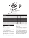
Proceed as follows to inspect and prepare the unit for initial
startup:
1. Remove access panel.
2. Read and follow instructions on all WARNING, CAUTION,
and INFORMATION labels attached to, or shipped with, unit.
3. Make the following inspections:
a. Inspect for shipping and handling damages such as broken
lines, loose parts, disconnected wires, etc.
b. Inspect for oil at all refrigerant tubing connections and on
unit base. Detecting oil generally indicates a refrigerant
C99024
452=5v
457=7v
455=2v
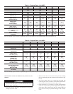
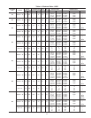
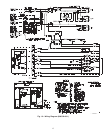
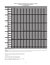
LEGEND
FLA — Full Load Amps
LRA — Locked Rotor Amps
MCA — Minimum Circuit Amps
MOCP — Maximum Overcurrent Protection
RLA — Rated Load Amps
NOTES:
1. In compliance with NEC (National Electrical Code) requirements
for multimotor and combination load equipment (refer to NEC
Articles 430 and 440), the overcurrent protective device for the
unit shall be Power Supply fuse. Canadian units may be
fuse or circuit breaker.
2. Minimum wire size is based on 60 C copper wire. If other than
60 C wire is used, or if length exceeds wire length in table,
determine size from NEC.
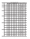
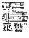
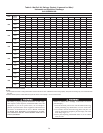
3. Unbalanced 3-Phase Supply Voltage
Never operate a motor where a phase imbalance in supply volt-
age is greater than 2%.
Use the following formula to determine
the percentage of voltage imbalance.
% Voltage imbalance
max voltage deviation from average voltage
= 100 x
average voltage
EXAMPLE: Supply voltage is 460-3-60.
AB = 452 v
BC = 464 v
AC = 455 v
452 + 464 + 455
Average Voltage =
3
1371
=
3
= 457
Determine maximum deviation from average voltage.
(AB) 457
(BC) 464
(AC) 457
Maximum deviation is 7 v.
Determine percent of voltage imbalance.
7
% Voltage Imbalance = 100 x
457
= 1.53%
This amount of phase imbalance is satisfactory as it is below the
maximum allowable 2%.
IMPORTANT: If the supply voltage phase imbalance is
more than 2%, contact your local electric utility company
immediately.
®
CKT BKR
—
Circuit Breaker
13