


45
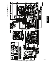
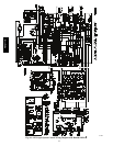
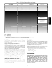
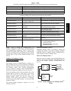
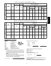
Table 10 – Unit Wire/Fuse or HACR Breaker Sizing Data
UNIT
NOM.
V --- Ph --- H z
IFM
TYPE
COMBUSTION
FAN MOTOR
POWER
EXHA UST
NO C.O. or UNPWR C.O.
FLA FLA
NO P.E. w/ P.E. (pwrd fr/ unit)
MCA
FUSE
or
HACR
BRKR
DISC. SIZE
MCA
FUSE
or
HACR
BRKR
DISC. SIZE
FLA LRA FLA LRA
48TC*D16
208/230---3---60
STD
0.48 3.8
68.3 80 71 396 72.1 80 76 400
MED 70.8 80 74 413 74.6 90 79 417
HIGH 81.2 100 86 432 85.0 100 91 436
460 --- 3 --- 60
STD
0.25 1.8
34 45 35 234 35.8 45 37 236
MED 35.0 45 37 243 36.8 45 39 245
HIGH 40.8 50 43 252 42.6 50 45 254
575 --- 3 --- 60
STD
0.24 3.8
26.5 30 28 184 30.3 40 32 188
MED 26.5 30 28 184 30.3 40 32 188
HIGH 32.7 40 35 196 36.5 45 39 200
Table 10 — Unit Wire/Fuse or HACR Breaker Sizing Data (cont)
UNIT
NOM.
V --- Ph --- H z
IFM
TYPE
COMBUSTION
FAN MOTOR
POWER
EXHA UST
w/ PWRD C.O.
FLA FLA
NO P.E. w/ P.E. (pwrd fr/ unit)
MCA
FUSE
or
HACR
BRKR
DISC. SIZE
MCA
FUSE
or
HACR
BRKR
DISC. SIZE
FLA LRA FLA LRA
48TC*D16
208/230---3---60
STD
0.48 3.8
73.1 80 77 401 76.9 100 81 405
MED 75.6 100 80 418 79.4 100 84 422
HIGH 86.0 100 92 437 89.8 100 96 441
460 --- 3 --- 60
STD
0.25 1.8
36.2 45 38 236 38 50 40 238
MED 37.2 50 39 245 39.0 50 41 247
HIGH 43.0 50 46 254 44.8 50 48 256
575 --- 3 --- 60
STD
0.24 3.8
28.2 35 30 186 32 40 34 190
MED 28.2 35 30 186 32 40 34 190
HIGH 34.4 40 37 198 38.2 45 41 202
Legend and Notes for Table 10
LEGEND:
BRKR --- Circuit breaker
CO --- Convenience outlet
DISC --- Disconnect
FLA --- Full load amps
IFM --- Indoor fan motor
LRA --- Locked rotor amps
MCA --- Minimum circuit amps
P.E. --- Power exhaust
PWRD CO --- Powered convenient outlet
UNPWR CO --- Unpowered c onvenient outlet
NOTES:
1. In compliance with NEC requirements for multimotor and
combination load equipment (refer to NEC Articles 430 and
440), the overcurrent protective device for the unit shall be
fuse or HACR breaker. Canadian units may be fuse or circuit
breaker.
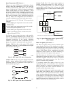
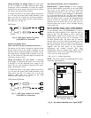
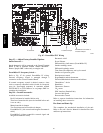
2. Unbalanced 3-Phase Supply Voltage
Never operate a motor where a phase imbalance in supply
voltage is greater than 2%. Use the following formula to de-
termine the percentage of voltage imbalance.
% VoltageImbalance = 100x
max voltage deviation fromaverage voltage
averagevoltage
Example: Supply voltage is 230-3-60
AB = 224 v
BC = 231 v
AC = 226 v
Average Voltage =
(224+ 231 +226)
=
681
3
3
= 227
Determine maximum deviation from average voltage.
(AB) 227 – 224 = 3 v
(BC) 231 – 227 = 4 v
(AC) 227 – 226 = 1 v
Maximum deviation is 4 v.
Determine percent of voltage imbalance.
% VoltageImbalance =100 x
4
227
=1.76%
This amount of phase imbalance is satisfactory as it is below the
maximum allowable 2%.
IMPORTANT: If the supply voltage phase imbalance is more than
2%, contact your local electric utility company immediately.
48TC**16