


37
Wiring the Indoor Air Quality Sensor: For each sensor,
use two 2--conductor 18 AWG (American Wire Gage)
twisted--pair cables (unshielded) to connect the separate
isolated 24 vac power source to the sensor and to connect
the sensor to the control board terminals.
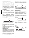
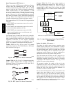
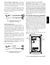
To connect the sensor to the control, identify the positive
(4 to 20 mA) and ground (SIG COM) terminals on the
sensor. See Fig. 54. Connect the 4--20 mA terminal to
RTU Open J4--2 and connect the SIG COM terminal to
RTU Open J4--3. See Fig. 72.
4-20mA
SIG COM
J4-2
J4-3
IAQ Sensor
24 VAC
C10738
Fig. 72 -- RTU Open / Indoor CO
2
Sensor
(33ZCSENCO2) Connections
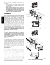
Outdoor Air Quality Sensor
(PNO 33ZCSENCO2 plus weatherproof enclosure) —
The outdoor air CO
2
sensor is designed to monitor carbon
dioxide (CO
2
) levels in the outside ventilation air and
interface with the ventilation damper in an HVAC system.
The OAQ sensor is packaged with an outdoor cover. See
Fig. 56. The outdoor air CO
2
sensor must be located in the
economizer outside air hood.
Wiring the Outdoor Air CO
2
Sensor: A dedicated
power supply is required for this sensor. A two--wire cable
is required to wire the dedicated power supply for the
sensor. The two wires should be connected to the power
supply and terminals 1 and 2.
To connect the sensor to the control, identify the positive
(4 to 20 mA) and ground (SIG COM) terminals on the
OAQ sensor. See Fig. 54. Connect the 4 to 20 mA
terminal to RTU Open J4--5. Connect the SIG COM
terminal to RTU Open J4--6. See Fig. 73.
4-20mA
SIG COM
J4-5
J4-6
OAQ Sensor/RH Sensor
24 VAC
C10739
Fig. 73 -- RTU Open / Outdoor CO
2
Sensor
(33ZCSENCO2) Connections
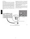
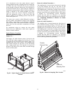
Space Relative Humidity Sensor or Humidistat —
Humidi--MiZer
R
Control Wiring: In units equipped
with the Humidi--MiZer option there are two pink (PNK)
wires loose in the control box used to control the
dehumidification function of the unit. These pink wires
are meant to be tied to a space humidistat or thermidistat
on an electromechanical unit. On RTU Open equipped
units these pink wires must be connected to J11--7 & 8 to
allow the Open board to operate the dehumidification
function for the unit. Disconnect the J11 Phoenix style
connector from the board and use the plug screws to
secure the pink wires in pins 7 and 8, reconnect the plug
to the board at J11.
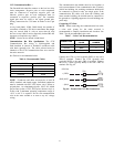
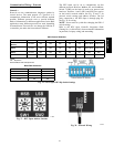
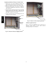
Relative Humidity Sensors (Space or Duct Mounted):
The accessory space humidity sensor (33ZCSENSRH-01)
or duct humidity sensor (33ZCSENDRH-01) is used to
measure the relative humidity of air within the space or
return air duct. The RH reading is used to control the
Humidi--MiZer option of the rooftop unit. For wiring
distances up to 500 ft (152 m), use a 3--conductor, 18 or
20 AWG shielded cable. The shield must be removed
from the sensor end of the cable and grounded at the unit
end. The current loop power for sensor is provided by the
RTU Open controller as 24vdc. Refer to the instructions
supplied with the RH sensor for the electrical
requirements and terminal locations. RTU Open
configurations must be changed after adding an RH
sensor. See Fig. 74 and 75 for typical RH sensor wiring.
S J4--1 or J4--4 = 24vdc loop power
S J4--2 or J4--5 = 4--20mA signal input
NOTE: The factory default for dehumidification control
is normally open humidistat.
SW2
123456
ON
Io
Vin
Gnd
Vo
MOUNTING
HOLES
WIRING
OPENING
Vin - J4-1 or J4-4 24Vdc
Io - J4-2 or J4-5 -20mA output
C11087
Fig. 74 -- Space Relative Humidity Sensor Typical Wiring
48TC**16