


30
Smoke Detector/Fire Shutdown (FSD) —
This function is available only when PremierLink is
configured for (Space) Sensor Mode. The unit is
factory--wired for PremierLink FSD operation when
PremierLink is factory--installed.
On 48TC**16 units equipped with factory--installed
Smoke Detector(s), the smoke detector controller
implements the unit shutdown through its NC contact set
connected to the unit’s CTB input. The FSD function is
initiated via the smoke detector’s Alarm NO contact set.
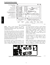
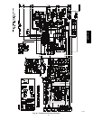
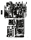
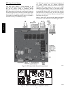
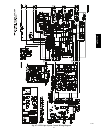
The PremierLink communicates the smoke detector’s
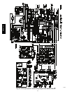
tripped status to the CCN building control. See Fig. 46,
the PremierLink wiring schematic.
Filter Status Switch —
This function is available only when PremierLink is
configured for (Space) Sensor Mode.
PremierLink control can monitor return filter status in two
ways: By monitoring a field--supplied/installed filter
pressure switch or via supply fan runtime hours.
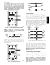
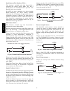
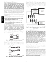
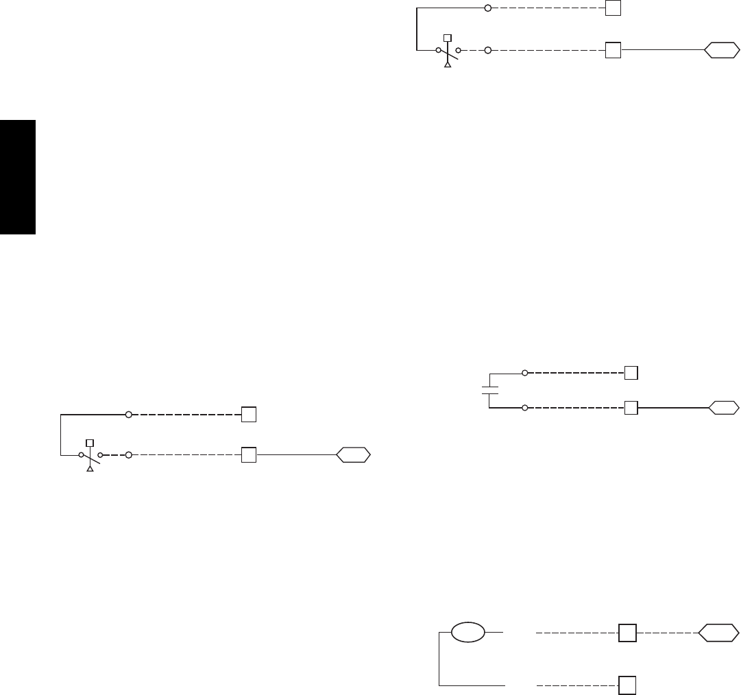
Using switch input: Install the dirty filter pressure switch
according to switch manufacturer’s instructions, to
measure pressure drop across the unit’s return filters.
Connect one side of the switch’s NO contact set to CTB’s
THERMOSTAT--R terminal. Connect the other side of the
NO contact set to TB3--10. Setpoint for Dirty Filter is set
at the switch. See Fig. 60.
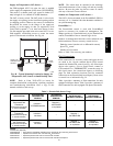
R
TB3
J4-4
PL
Filter Switch (NO, close on rising pressure (high drop))
CTB
Thermostat
10
C10286
Fig. 60 -- PremierLink Filter Switch Connection
When the filter switch’s NO contact set closes as filter
pressure drop increases (indicating dirt--laden filters), the
input signal to PremierLink causes the filter status point to
read “DIRTY”.
Using Filter Timer Hours: Refer to Form 33CS--67SI for
instructions on using the PremierLink Configuration
screens and on unit alarm sequence.
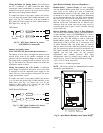
Supply Fan Status Switch —
The PremierLink control can monitor supply fan operation
through a field--supplied/installed differential pressure
switch. This sequence will prevent (or interrupt) operation
of unit cooling, heating and economizer functions until
the pressure switch contacts are closed indicating proper
supply fan operation.
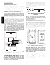
Install the differential pressure switch in the supply fan
section according to switch manufacturer’s instructions.
Arrange the switch contact to be open on no flow and to
close as pressure rises indicating fan operation.
Connect one side of the switch’s NO contact set to CTB’s
THERMOSTAT--R terminal. Connect the other side of the
NO contact set to TB3--8. Setpoint for Supply Fan Status
is set at the switch. See Fig. 61.
R
TB3
J4-6
PL
Fan (Pressure) Switch (NO, close on rise in pressure)
CTB
Thermostat
8
C10287
Fig. 61 -- PremierLink Wiring Fan Pressure Switch
Connection
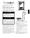
Remote Occupied Switch —
The PremierLink control permits a remote timeclock to
override the control’s on--board occupancy schedule and
place the unit into Occupied mode. This function may also
provide a “Door Switch” time delay function that will
terminate cooling and heating functions after a 2--20 minute
delay.
Connect one side of the NO contact set on the timeclock
to CTB’s THERMOSTAT--R terminal. Connect the other
side of the timeclock contact to the unit’s TB3--2 terminal.
See Fig. 62.
R
2
TB3
PL
Time Clock
Remote Occupied
LCTB
Thermostat
J4-12
C10288
Fig. 62 -- PremierLink Wiring Remote Occupied
Refer to Form 33CS--67SI for additional information on
configuring the PremierLink control for Door Switch
timer function.
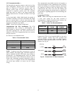
Power Exhaust (output) —
Connect the accessory Power Exhaust contactor coils(s)
per Fig. 63.
J8-3
15
C
TB3
PL
PEC
TAN
Power Exhaust
CTB
THERMOSTAT
GRA
C10289
Fig. 63 -- PremierLink Power Exhaust Output
Connection
48TC**16