


16
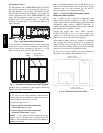
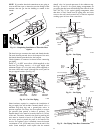
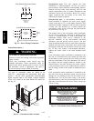
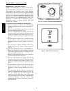
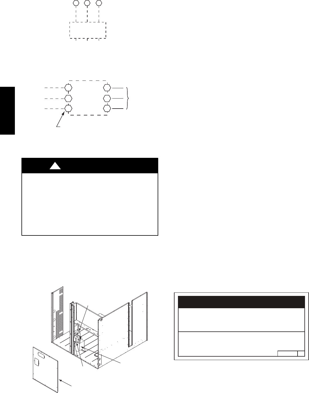
Units Without Disconnect Option
Units With Disconnect Option
2
4
6
1
3
5
L1
L2
L3
Optional
Disconnect
Switch
Disconnect factory test leads; discard.
Factory
Wiring
11 12 13
L1
L2 L3
TB1
208/230-3-60
460-3-60
575-3-60
Disconnect
per
NEC
C10015
Fig. 31 -- Power Wiring Connections
Convenience Outlets —
ELECTRICAL OPERATION HAZARD
Failure to follow this warning could result in personal
injury or death.
Units with convenience outlet circuits may use
multiple disconnects. Check convenience outlet for
power status before opening unit for service. Locate
its disconnect switch, if appropriate, and open it.
Lock--out and tag--out this switch, if necessary.
!
WARNING
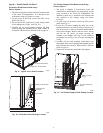
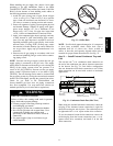
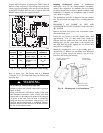
Two types of convenience outlets are offered on the
48TC**16 : non--powered and unit--powered. Both types
provide a 125--volt GFCI (ground--fault circuit--interrupter)
duplex receptacle rated at 15--A behind a hinged waterproof
access cover, located on the panel beneath the control box.
See Fig. 32.
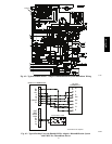
Convenience
Outlet
GFCI
Pwd-CO
Fuse
Switch
Pwd-CO
Transformer
Disconnect
Access Panel
C10361
Fig. 32 -- Convenience Outlet Location
Non--powered type: This type requires the field
installation of a general--purpose 125--volt 15--A circuit
powered from a source elsewhere in the building. Observe
national and local codes when selecting wire size and
conduit requirements, fuse or breaker requirements and
disconnect switch size and location. Route 125--v power
supply conductors into the bottom of the utility box
containing the duplex receptacle.
Unit--powered type: A unit--mounted transformer is
factory--installed to stepdown the main power supply
voltage to the unit to 115--v at the duplex receptacle. This
option also includes a manual switch with fuse, located in
a utility box and mounted on a bracket behind the
convenience outlet; access is through the panel beneath
the control box. See Fig. 32.
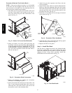
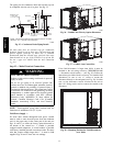
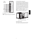
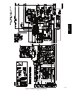
The primary leads to the convenience outlet transformer
are not factory--connected. Selection of primary power
source is a customer--option. If local codes permit, the
transformer primary leads can be connected at the
line--side terminals on the unit--mounted non--fused
disconnect; this will provide service power to the unit
when the unit disconnect switch is open. Other connection
methods will result in the convenience outlet circuit being
de--energized when the unit disconnect switch is open. See
Fig. 34. On a unit without a unit--mounted disconnect,
connect the source leads to the main terminal block
(TB1).
If the convenience outlet transformer is connected to the
line side of a field disconnect, the conduit provided with
the unit must be used to protect the wire as they are routed
from the transformer to the field disconnect. The end of
the conduit with the straight connector attaches to the
field disconnect. The other end does not need to connect
to the transformer; however, the conduit must be routed so
that all wiring is either in the conduit or behind the access
panel.
If the convenience outlet transformer is connected to the
line side of the factory disconnect option, route the wires
through the web bushing located on the bottom of the
disconnect box. For the load side wiring to the factory
option disconnect, route the wires through the hole on the
right side of the disconnect. Be sure to create a drip loop
at least 6” long.
2.050HE501288
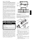
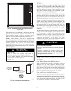
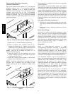
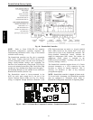
NOTICE/AVIS
Convenience Outlet Utilization
Maximum Intermittent Use 15 - Amps
Maximum Continuous Use 8 - Amps
Observe a 50% limit on the circuit
Loading above 8 - Amps
Utilisation de la prise utilitaire
Usage intermittent maximum 15 - Amps
Usage continu maximum 8 - Amps
Observez une limite de 50% sur le circuit
Chargement au-dessus de 8 - Amps
C10077
Fig. 33 -- Convenience Outlet Utilization Notice
48TC**16