


36
Space Temperature (SPT) Sensors —
There are two types of SPT sensors available from Carrier,
resistive input non-communicating (T55, T56, and T59)
and Rnet communicating (SPS, SPPL, SPP, and SPPF)
sensors. Each type has a variety of options consisting of:
timed override button, set point adjustment, a LCD
screen, and communication tie in. Space temperature can
be also be written to from a building network or zoning
system. However, it is still recommended that return air
duct sensor be installed to allow stand-alone operation for
back-up. Refer to the configuration section for details on
controller configurations associated with space sensors.
Field connections to T--55, T--56 and T--59 are provided as
examples.
S 33ZCT55SPT, space temperature sensor with override
button (T--55)
S 33ZCT56SPT, space temperature sensor with override
button and setpoint adjustment (T--56)
S 33ZCT59SPT, space temperature sensor with LCD
(liquid crystal display) screen, override button, and
setpoint adjustment (T--59)
Use 20 gauge wire to connect the sensor to the controller.
The wire is suitable for distances of up to 500 ft. Use a
three--conductor shielded cable for the sensor and setpoint
adjustment connections. If the setpoint adjustment
(slidebar) is not required, then an unshielded, 18 or 20
gauge, two--conductor, twisted pair cable may be used.
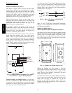
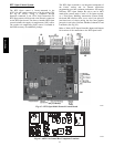
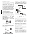
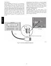
Connect T--55: See Fig. 49 for typical T--55 internal
connections. Connect the T--55 SEN terminals to RTU Open
J20--1 and J20--2. See Fig. 69.
SEN
SEN
J20-1
J20-2
C08460
Fig. 69 -- RTU Open T--55 Sensor Connections
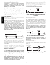
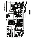
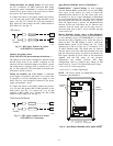
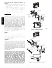
Connect T--56: See Fig. 51 for T--56 internal connections.
Install a jumper between SEN and SET terminals as
illustrated. Connect T--56 terminals to RTU Open J20--1,
J20--2 and J20--3 per Fig. 70.
SEN J20-1
J20-2
SEN
SET
Jumper
J20-3
SET
C08461
Fig. 70 -- RTU Open T--56 Sensor Connections
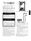
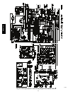
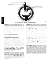
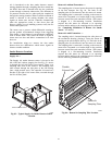
Connect T--59: The T--59 space sensor requires a
separate, isolated power supply of 24 VAC. See Fig. 71
for internal connections at the T--59. Connect the SEN
terminal (BLU) to RTU Open J20--1. Connect the COM
terminal (BRN) to J20--2. Connect the SET terminal (STO
or BLK) to J20--3.
OR SET SEN
OPB COM- PWR+
BLU (SPT)
BLK (STO)
24 VAC
SENSOR
WIRING
POWER
WIRING
BRN (COM)
NOTE: Must use a separate isolated transformer.
J20-3
J20-2
J20-1
C10291
Fig. 71 -- Space Temperature Sensor Typical Wiring
(33ZCT59SPT)
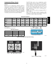
Indoor Air Quality (CO
2
sensor) —
The indoor air quality sensor accessory monitors space
carbon dioxide (CO
2
) levels. This information is used to
monitor IAQ levels. Several types of sensors are available,
for wall mounting in the space or in return duct, with and
without LCD display, and in combination with space
temperature sensors. Sensors use infrared technology to
measure the levels of CO
2
present in the space air.
The CO
2
sensors are all factory set for a range of 0 to
2000 ppm and a linear mA output of 4 to 20. Refer to the
instructions supplied with the CO
2
sensor for electrical
requirements and terminal locations. See Fig. 54 for
typical CO
2
sensor wiring schematic.
To accurately monitor the quality of the air in the
conditioned air space, locate the sensor near a return--air
grille (if present) so it senses the concentration of CO
2
leaving the space. The sensor should be mounted in a
location to avoid direct breath contact.
Do not mount the IAQ sensor in drafty areas such as near
supply ducts, open windows, fans, or over heat sources.
Allow at least 3 ft (0.9 m) between the sensor and any
corner. Avoid mounting the sensor where it is influenced
by the supply air; the sensor gives inaccurate readings if
the supply air is blown directly onto the sensor or if the
supply air does not have a chance to mix with the room air
before it is drawn into the return airstream.
48TC**16