


29
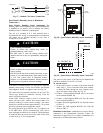
SEN J5-2
J5-3
COM
13
11
TB3
TB3
IAQ Sensor
PL
24 VAC
C10285
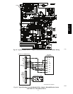
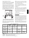
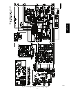
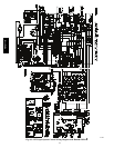
Fig. 57 -- Outdoor CO
2
Sensor Connections
Space Relative Humidity Sensor or Humidistat
Connections —
Space Relative Humidity Sensor connections: The
accessory space relative humidity sensor (33ZCSENSRH-01)
is installed on an interior wall to measure the relative
humidity of the air within the occupied space.
The use of a standard 2 X 4 inch electrical box to
accommodate the wiring is recommended for installation.
The sensor can be mounted directly on the wall, if
acceptable by local codes.
UNIT DAMAGE HAZARD
Failure to follow this caution may result in
permanent damage to the sensor.
DO NOT clean or touch the sensing element with
chemical solvents as they can permanently damage the
sensor.
CAUTION
!
UNIT PERFORMANCE HAZARD
Failure to follow this caution will result in inaccurate
sensor readings.
DO NOT mount the sensor in drafty areas such as near
heating or air--conditioning ducts, open windows, fans,
or over heat sources such as baseboard heaters,
radiators, or wall--mounted dimmers. Sensors mounted
in those areas will produce inaccurate readings.
CAUTION
!
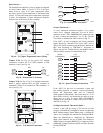
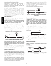
If the sensor is installed directly on a wall service, install the
humidity sensor using 2 screws and 2 hollow wall anchors
(field supplied). Do not over tighten screws. See Fig. 58.
The sensor must be mounted vertically on the wall. The
Carrier logo should be orientated correctly when the
sensor is properly mounted.
Avoid corner locations. Allow at least 4 ft between the
sensor and any corner. Airflow near corners tends to be
reduced, resulting in erratic sensor readings. The sensor
should be vertically mounted approximately 5 ft up from
the floor, beside the space temperature sensor.
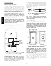
For wiring distances up to 500 feet, use a 3--conductor, 18
or 20 AWG cable. ACCN communication cable can be
used, although the shield is not required. The shield must
be removed from the sensor end of the cable if this cable
is used. See Fig. 59 for wiring details.
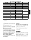
SW2
123456
ON
Io
Vin
Gnd
Vo
MOUNTING
HOLES
WIRING
OPENING
C11084
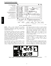
Fig. 58 -- Space Relative Humidity Sensor Installation
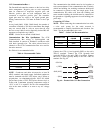
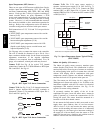
Io VoVin Gnd
BLACK
RED
TB3-7
TB3-13
C11085
Fig. 59 -- Space Relative Humidity Sensor Connection
The power for the sensor is provided by the PremierLink
control on terminal J5--4 (+33 to +35vdc).
To wire the sensor:
1. At the sensor, remove 4 inches of the jacket from the
cable. Strip
1
/
4
inch of insulation from each conduct-
or. Route the cable through the wire clearance open-
ing in the center of the sensor. See Fig. 58.
2. Connect a field--supplied BLACK wire to the sensor
screw terminal marked Vin.
3. Connect a field--supplied RED wire into the sensor
screw terminal marked Io.
4. Connect the field--supplied RED wire from the sensor
to TB3--13.
5. Connect the field--supplied BLACK wire from the
sensor to TB3--7.
Humidistat connections: A humidistat can not be directly
connected to the PremierLink controller. Follow the
instructions on pages 20 & 21 to connect a humidistat or a
thermostat as an electromechanical device.
48TC**16