


13
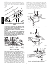
When installing the gas supply line, observe local codes
pertaining to gas pipe installations. Refer to the NFPA
54/ANSI Z223.1 NFGC latest edition (in Canada, CAN/CSA
B149.1). In the absence of local building codes, adhere to
the following pertinent recommendations:
1. Avoid low spots in long runs of pipe. Grade all pipe
1
/4--in. in every 15 ft (7 mm in every 5 m) to prevent
traps. Grade all horizontal runs downward to risers.
Use risers to connect to heating section and to meter.
2. Protect all segments of piping system against physical
and thermal damage. Support all piping with appro-
priate straps, hangers, etc. Use a minimum of one
hanger every 8 ft (2.4 m). For pipe sizes larger than
3
/4--in., follow recommendations of national codes.
3. Apply joint compound (pipe dope) sparingly and only
to male threads of joint when making pipe connec-
tions. Use only pipe dope that is resistant to action of
liquefied petroleum gases as specified by local and/or
national codes. If using PTFE (Teflon) tape, ensure
the material is Double Density type and is labeled for
use on gas lines. Apply tape per manufacturer’s in-
structions.
4. Pressure--test all gas piping in accordance with local
and national plumbing and gas codes before connect-
ing piping to unit.
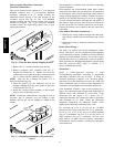
NOTE: Pressure test the gas supply system after the gas
supply piping is connected to the gas valve. The supply
piping must be disconnected from the gas valve during the
testing of the piping systems when test pressure is in
excess of 0.5 psig (3450 Pa). Pressure test the gas supply
piping system at pressures equal to or less than 0.5 psig
(3450 Pa). The unit heating section must be isolated from
the gas piping system by closing the external main manual
shutoff valve and slightly opening the ground--joint union.
Check for gas leaks at the field--installed and
factory--installed gas lines after all piping connections
have been completed. Use soap--and--water solution (or
method specified by local codes and/or regulations).
FIRE OR EXPLOSION HAZARD
Failure to follow this warning could result in personal
injury, death and/or property damage.
S Connect gas pipe to unit using a backup wrench to
avoid damaging gas controls.
S Never purge a gas line into a combustion chamber.
S Never test for gas leaks with an open flame. Use a
commercially available soap solution made
specifically for the detection of leaks to check all
connections.
S Use proper length of pipe to avoid stress on gas
control manifold.
!
WARNING
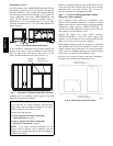
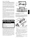
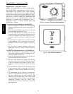
BURNER
ORIFICE
A93059
Fig. 23 -- Orifice Hole
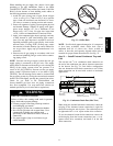
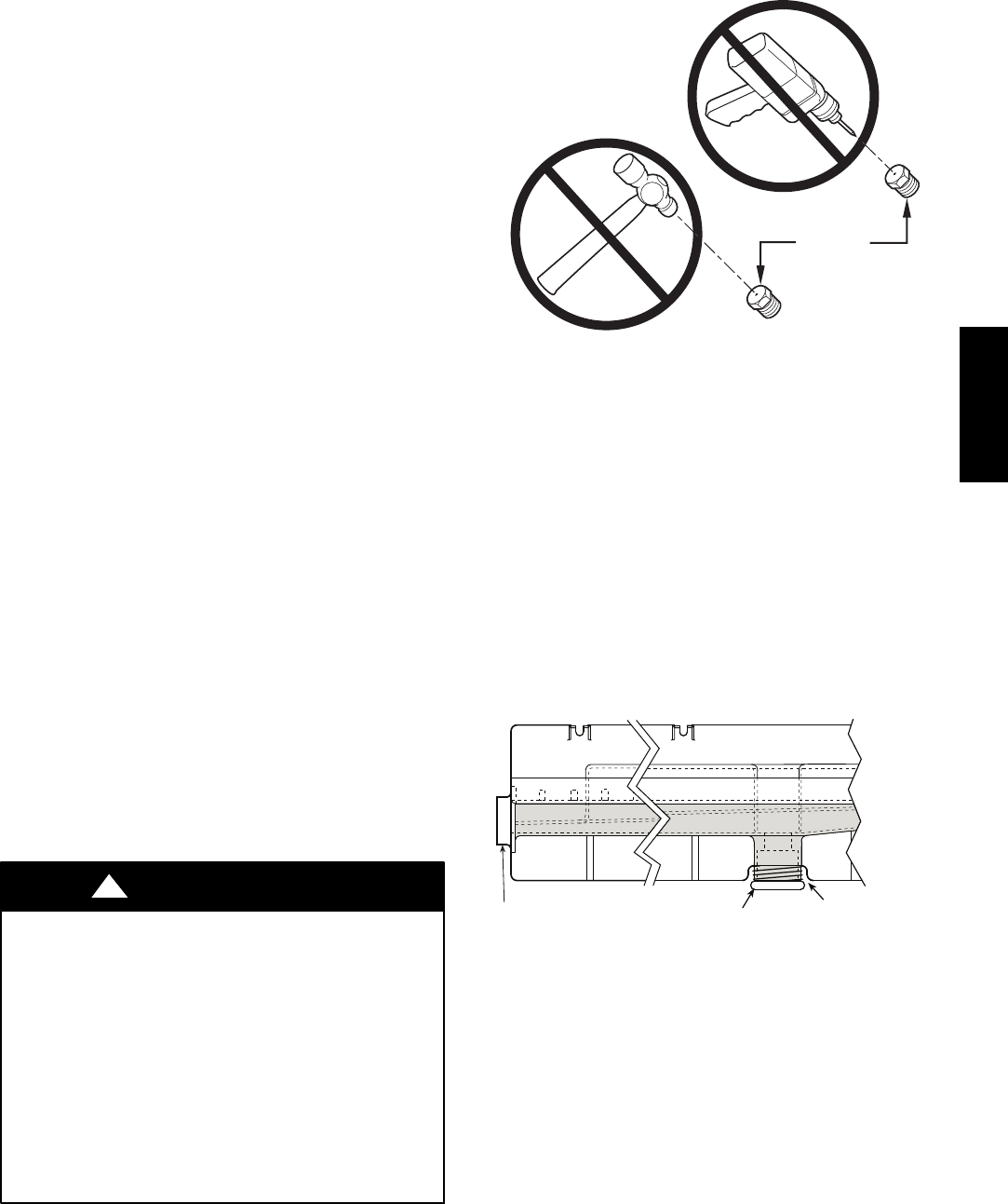
NOTE: If orifice hole appears damaged or it is suspected
to have been re--drilled, check orifice hole with a
numbered drill bit of correct size. Never re--drill an
orifice. A burr--free and squarely aligned orifice hole is
essential for proper flame characteristics. See Fig. 23.
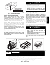
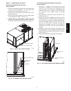
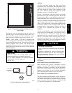
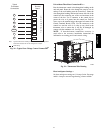
Step 11 — Install External Condensate Trap and
Line
The unit has one
3
/
4
-in. condensate drain connection on
the end of the condensate pan and an alternate connection
on the bottom. See Fig. 24. Unit airflow configuration
does not determine which drain connection to use. Either
drain connection can be used with vertical or horizontal
applications.
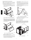
DRAIN
(FACTORY-INSTALLED)
PLUG
CONDENSATE PAN (SIDE VIEW)
STANDARD
SIDE DRAIN
ALTERNATE
BOTTOM DRAIN
C08021
Fig. 24 -- Condensate Drain Pan (Side View)
When using the standard side drain connection, ensure the
red plug in the alternate bottom connection is tight. Do
this before setting the unit in place. The red drain pan can
be tightened with a
1
/
2
--in. square socket drive extension.
To use the alternate bottom drain connection, remove the
red drain plug from the bottom connection (use a
1
/
2
-- i n .
square socket drive extension) and install it in the side
drain connection.
48TC**16