


11
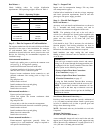
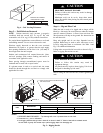
Step 10 — Install Gas Piping
Installation of the gas piping must be accordance with
local building codes and with applicable national codes.
In U.S.A., refer to NFPA 54/ANSI Z223.1 National Fuel
Gas Code (NFGC). In Canada, installation must be
accordance with the CAN/CSA B149.1 and CAN/CSA
B149.2 installation codes for gas burning appliances.
This unit is factory equipped for use with Natural Gas fuel
at elevations up to 2000 ft (610 m) above sea level. Unit
may be field converted for operation at elevations above
2000 ft (610 m) and/or for use with liquefied petroleum
fuel. See accessory kit installation instructions regarding
these accessories.
NOTE: In U.S.A. the input rating for altitudes above 2000
ft (610 m) must be derated by 4% for each 1000 ft (305 m)
above sea level. In Canada the input rating must be derated
by 10% for altitudes of 2000 ft (610 m) to 4500 ft. (1372 m)
above sea level.
For natural gas applications, gas pressure at unit gas
connection must not be less than 5 in. wg (1250 Pa) or
greater than 13 in. wg (3240 Pa) while the unit is operating.
For liquified petroleum applications, the gas pressure must
not be less than 11 in. wg (2740 Pa) or greater than 13 in.
wg (3240 Pa) at the unit connection.
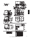
The gas supply pipe enters the unit at the burner access
panel on the front side of the unit, through the long slot at
the bottom of the access panel. The gas connection to the
unit is made to the
3
/4--in. FPT gas inlet port on the unit gas
valve.
Table 2 – Natural Gas Supply Line Pressure Ranges
UNIT MIN MAX
48HC**14 5.0 in. wg (1250 Pa) 13.0 in. wg (3240 Pa)
EQUIPMENT DAMAGE HAZARD
Failure to follow this caution may result in damage
to equipment.
When connecting the gas line to the unit gas valve,
the installer MUST use a backup wrench to prevent
damage to the valve.
CAUTION
!
Install a gas supply line that runs to the unit heating
section. Refer to the NFPA 54/NFGC or equivalent code
for gas pipe sizing data. Size the gas supply line to allow
for a maximum pressure drop of 0.5--in wg (124 Pa)
between gas regulator source and unit gas valve
connection when unit is operating at high--fire flow rate.
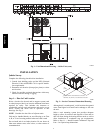
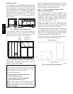
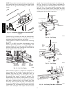
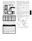
The gas supply line can approach the unit in three ways:
horizontally from outside the unit (across the roof),
thru--curb/under unit basepan (accessory kit required) or
through unit basepan (factory--option or accessory kit
required). Consult accessory kit installation instructions
for details on these installation methods. Observe
clearance to gas line components per Fig. 16.
LEGEND
*
Field supplied.
NOTE:Follow all local codes.
NFGC – National Fuel Gas Code
STEEL PIPE
NOMINAL DIAMETER
(in.)
SPACINGOFSUPPORTS
X DIMENSION
(ft)
1
/
2
3
/
4
or 1
1
1
/
4
or larger
6
8
10
X
BASE UNIT
BASE RAIL
ROOF
CURB
9” MINIMUM CLEARANCE
FOR PANEL REMOVAL
MANUAL GAS
SHUTOFF VALVE
*
GAS
REGULATOR
*
48” MINIMUM
DRIP LEG
PER NFGC
*
FIELD-
FABRICATED
SUPPORT
*
FROM
GAS
METE
R
C11121
Fig. 16 -- Gas Piping Guide
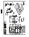
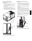
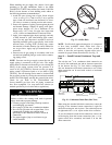
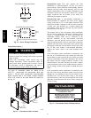
Factory--Option Thru--Base Connections
(Gas Connection) —
This service connectionkit consistsof a
3
/
4
--inNPT gasadapter
fitting (stainless steel), a
1
/
2
--in electrical bulkhead connector
and a 1
1
/
2
--in electrical bulkhead connector, connected to an
“L” bracket covering the embossed (raised) section of the unit
basepan in the condenser section. See Fig. 17.
1
1
/
2
” ELECTRICAL
BULKHEAD
CONNECTOR
1
/
2
” ELECTRICAL
BULKHEAD
CONNECTOR
3
/
4
” NPT GAS
ADAPTER
FITTING
C10905
Fig. 17 -- Thru--the--Base Option, Shipping Position
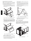
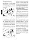
1. Remove the “L” bracket assembly from the unit (see
Fig. 17).
2. Cut and discard the wire tie on the gas fitting. Hand
tighten the fitting if it has loosened in transit.
3. Remove connector plate assembly from the “L”
bracket and discard the “L” bracket, but retain the
washer head screws and the gasket (located between
the “L” bracket and the connector plate assembly
NOTE: Take care not to damage the gasket, as it is
reused in the following step.
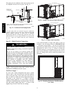
4. Place the gasket over the embossed area in the
basepan, aligning the holes in the gasket to the holes
in the basepan. See Fig. 18.
5. Install the connector plate assembly to the basepan
using 8 of the washer head screws.
48TC**16