


19
X
C
G
W2
C
W2
G
W1
O/B/Y2
Y2
R
W1
R
Y1
Y1
T
H
E
R
M
O
S
T
A
T
(see Note)
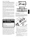
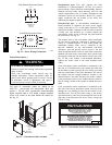
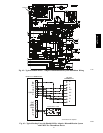
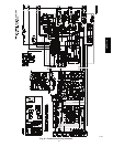
Note: Typical multi-function marking. Follow manufacturer’s configuration
instructions to select Y2. Do not configure for O output.
Field Wiring
Central
Terminal
Board
Typical
Thermostat
Connections
C10903
Fig. 38 -- Typical Low--Voltage Control Connections
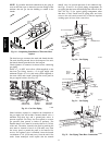
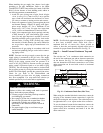
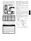
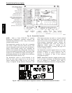
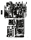
Unit without Thru--Base Connection Kit —
Pass the thermostat control wires through the bushing on the
unit end panel. Route the wire through the snap--in wire tie
and up to the web bushing near the control box.. Route the
wire through the bushing and into the bottom left side of the
control box after removing one of the two knockouts in the
corner of the box. Use a connector at the control box to
protect the wire as it passes into the control box. Pull the
wires over to the terminal strip at the upper left corner of the
Central Terminal Board (CTB). Use the connector at the
control box and the wire tie to take up any slack in the
thermostat wire to ensure that it will not be damaged by
contact with the condenser coil. See Fig. 39.
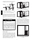
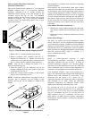
NOTE: If thru--the--bottom connections accessory is
used, refer to the accessory installation instructions for
information on routing power and control wiring.
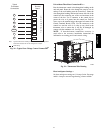
Thermostat Wire
C10886
Fig. 39 -- Thermostat Wire Routing
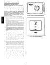
Heat Anticipator Settings —
Set heat anticipator settings at 0.14 amp for the first stage
and 0.14 amp for second--stage heating, when available.
48TC**16