


12
NOTE: If gas and/or electrical connections are not going to
occur at this time, tape or otherwise cover the fittings so that
moisture does not get into the building or conduit in the
interim.
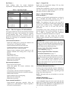
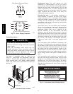
GASKET
CONNECTOR
PLATE
ASSEMBLY
C10906
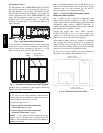
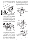
Fig. 18 -- Completing Installation of Thru--the--Base
Option
The thru--base gas connector has male and female threads.
The male threads protrude above the basepan of the unit;
the female threads protrude below the basepan.
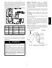
Check tightness of connector lock nuts before connecting
gas piping.
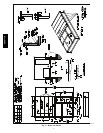
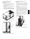
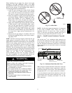
Install a
3
/
4
--in NPT street elbow (field--supplied) on the
thru--base gas fitting. Attach a
3
/
4
--in pipe nipple with
minimum length of 16--in (406 mm) (field--supplied) to
the street elbow and extend it through the access panel at
the gas support bracket. (See Fig. 19.)
3
/
4
-in NPT
STREET
ELBOW
THRU-BASE
GAS FITTING
GAS
SUPPORT
BRACKET
C10806
Fig. 19 -- Gas Line Piping
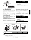
Other hardware required to complete the installation of
the gas supply line will include a manual shutoff valve, a
sediment trap (drip leg) and a ground--joint union. A
pressure regulator valve may also be required (to convert
gas pressure from pounds to inches of pressure). The
manual shutoff valve must be located within 6--ft (1.83 m)
of the unit. The union, located in the final leg entering the
unit, must be located at least 9--in (230 mm) away from
the access panel to permit the panel to be removed for
service. If a regulator valve is installed, it must be located
a minimum of 4--ft (1220 mm) away from the unit’s flue
outlet. Some municipal codes require that the manual
shutoff valve be located upstream of the sediment trap.
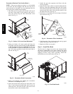
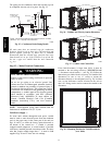
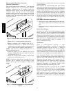
See Figs. 20 and 21 for typical piping arrangements for
gas piping that has been routed through the sidewall of the
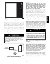
curb. See Fig. 22 for typical piping arrangement when
thru--base is used. Ensure that all piping does not block
access to the unit’s main control box or limit the required
working space in front of the control box.
9” (229mm) min
Union
Shut Off
Valve
Drip
Leg
Thru-Curb Adapter
Unit Base Rail
C07469
Fig. 20 -- Gas Piping
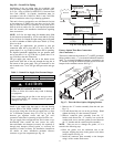
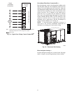
Drip
Leg
Shut Off
Valve
Union
Thru-Curb Adapter
Burner
Access
Panel
9” (229mm) min
Unit Base Rail
C07470
Fig. 21 -- Gas Piping
C10826
Fig. 22 -- Gas Piping Thru--Base Connections
48TC**16