


27
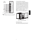
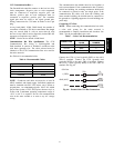
Space Sensors —
The PremierLink controller is factory--shipped configured
for Space Sensor Mode. A Carrier T--55 or T--56 space
sensor must be used. T--55 space temperature sensor
provides a signal of space temperature to the PremierLink
control. T--56 provides same space temperature signal plus
it allows for adjustment of space temperature setpoints
from the face of the sensor by the occupants.
2
3
45
61
SW1
SEN
BRN (GND)
BLU (SPT)
RED(+)
WHT(GND)
BLK(-)
CCN COM
SENSOR WIRING
C08201
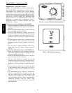
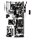
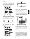
Fig. 49 -- T--55 Space Temperature Sensor Wiring
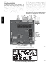
Connect T--55: See Fig. 49 for typical T--55 internal
connections. Connect the T--55 SEN terminals to TB3
terminals 1 and 3 (see Fig. 50).
SEN J6-7
J6-6
1
3
TB3 PL
SEN
C10023
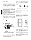
Fig. 50 -- PremierLink T--55 Sensor
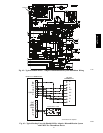
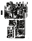
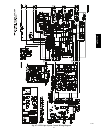
Connect T--56: See Fig. 51 for T--56 internal connections.
Install a jumper between SEN and SET terminals as
illustrated. Connect T--56 terminals to TB3 terminals 1, 3
and 5 (see Fig. 52).
2
3
45
61
SW1
SEN
SET
Cool Warm
BRN (GND)
BLU (SPT)
RED(+)
WHT(GND)
BLK(-)
CCN COM
SENSOR WIRING
JUMPER
TERMINALS
AS SHOWN
BLK
(T56)
C08202
Fig. 51 -- T--56 Internal Connections
SEN J6-7
J6-6
1
3
TB3 PL
SEN
SET
Jumper
TB3
PL
J6-5
5
SET
C10022
Fig. 52 -- PremierLink T--56 Sensor
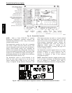
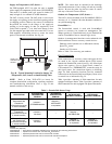
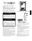
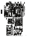
Connect Thermostat —
A 7--wire thermostat connection requires a 24--v power
source and a common connection. Use the R and C
terminals on the CTB’s THERMOSTAT connection strip
for these. Connect the thermostat’s Y1, Y2, W1, W2 and
G terminals to PremierLink TB3 as shown in Fig. 53.
If the 48TC**16 unit is equipped with factory--installed
smoke detector(s), disconnect the factory BLU lead at
TB3--6 (Y2) before connecting the thermostat. Identify the
BLU lead originating at CTB--DDC--1; disconnect at
TB3--6 and tape off. Confirm that the second BLU lead at
TB3--6 remains connected to PremierLink J4--8.
GJ4-12
J4-10
J4-8
Y1
Y2
2
R
R
4
6
J4-6
J4-4
W2
C
8
10
C
SPACE
THERMOSTAT
CTB
THERMOSTAT
PL
W1
TB3
CTB
THERMOSTAT
C10283
Fig. 53 -- Space Thermostat Connections
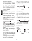
If the 48TC**16 unit has an economizer system and
free--cooling operation is required, a sensor representing
Return Air Temperature must also be connected
(field--supplied and installed). This sensor may be a T--55
Space Sensor (see Fig. 49) installed in the space or in the
return duct, or it may be sensor PNO 33ZCSENSAT,
installed in the return duct. Connect this sensor to TB3--1
and TB3--3 per Fig. 50.
Configure the unit for Thermostat Mode —
Connect to the CCN bus using a CCN service tool and
navigate to PremierLink Configuration screen for Operating
Mode. Default setting is Sensor Mode (value 1). Change the
value to 0 to reconfigure the controller for Thermostat Mode.
When the PremierLink is configured for Thermostat
Mode, these functions are not available: Fire Shutdown
(FSD), Remote Occupied (RMTOCC), Compressor Safety
(CMPSAFE), Supply Fan Status (SFS), and Filter Pressure
Switch (FILTER).
48TC**16