


31
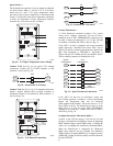
CCN Communication Bus —
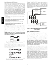
The PremierLink controller connects to the bus in a daisy
chain arrangement. Negative pins on each component
must be connected to respective negative pins, and
likewise, positive pins on each component must be
connected to respective positive pins. The controller
signal pins must be wired to the signal ground pins.
Wiring connections for CCN must be made at the 3--pin
plug.
At any baud (9600, 19200, 38400 baud), the number of
controllers is limited to 239 devices maximum. Bus length
may not exceed 4000 ft, with no more than 60 total
devices on any 1000--ft section. Optically isolated RS--485
repeaters are required every 1000 ft.
NOTE: Carrier device default is 9600 band.
Communications Bus Wire Specifications: The CCN
Communication Bus wiring is field--supplied and
field--installed. It consists of shielded 3--conductor cable
with drain (ground) wire. The cable selected must be
identical to the CCN Communication Bus wire used for
the entire network.
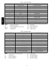
See Table 6 for recommended cable.
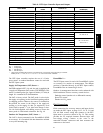
Table 6 – Recommended Cables
MANUF ACTURER CABLE PART NO.
Alpha 2413 or 5463
American A22503
Belden 8772
Columbia 02525
NOTE: Conductors and drain wire must be at least 20
AWG, stranded, and tinned copper. Individual conductors
must be insulated with PVC, PVC/nylon, vinyl, Teflon, or
polyethylene. An aluminum/polyester 100% foil shield
and an outer jacket of PVC, PVC/nylon, chrome vinyl, or
Teflon with a minimum operating temperature range of
-- 2 0 _Cto60_C is required. Do not run communication
wire in the same conduit as or next to any AC voltage
wiring.
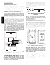
The communication bus shields must be tied together at
each system element. If the communication bus is entirely
within one building, the resulting continuous shield must
be connected to ground at only one single point. If the
communication bus cable exits from one building and
enters another building, the shields must be connected to
the grounds at a lightning suppressor in each building (one
point only).
Connecting CCN Bus:
NOTE: When connecting the communication bus cable,
a color code system for the entire network is
recommended to simplify installation and checkout. See
Table 7 for the recommended color code.
Table 7 – Color Code Recommendations
SIGNAL TYPE
CCN BUS WIRE
COLOR
CCN PLUG PIN
NUMBER
+ Red 1
Ground White 2
--- Black 3
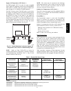
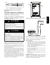
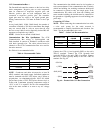
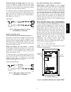
Connect the CCN (+) lead (typically RED) to the unit’s
TB3--12 terminal. Connect the CCN (ground) lead
(typically WHT) to the unit’s TB3--14 terminal. Connect
the CCN (--) lead (typically BLK) to the unit’s TB3--16
terminal. See Fig. 64.
CCN Bus
J2-1
J2-2GND (WHT)
12
14
TB3
J2-3– (BLK) 16
TB3
TB3
PL
+ (RED)
C10290
Fig. 64 -- PremierLink CCN Bus Connections
48TC**16