


8
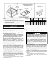
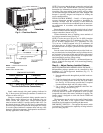
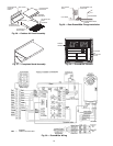
Install conduit through side panel openings indicated in
Fig. 5. Route power lines through connector to terminal con-
nections as shown in Fig. 8.
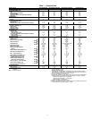
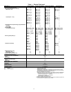
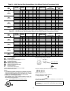
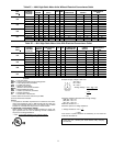
Voltage to compressor terminals during operation must be
within voltage range indicated on unit nameplate (also see
Tables 2A-2D). On 3-phase units, voltages between phases
must be balanced within 2% and the current within 10%. Use
the formula shown in Tables 2A-2D, Note 2 to determine the
percent voltage imbalance. Operation on improper line voltage
or excessive phase imbalance constitutes abuse and may cause
damage to electrical components. Such operation would invali-
date any applicable Carrier warranty.
NOTE: If accessory thru-the-bottom connections and roof curb
are used, refer to the Thru-the-Bottom Accessory Installation
Instructions for information on power wiring and gas connec-
tion piping. The power wiring, control wiring and gas piping
can be routed through field-drilled holes in the basepan. The
basepan is specially designed and dimpled for drilling the
access connection holes.
FIELD CONTROL WIRING — Install a Carrier-approved
accessory thermostat assembly according to installation in-
structions included with the accessory. Locate thermostat
assembly on a solid wall in the conditioned space to sense aver-
age temperature in accordance with thermostat installation
instructions.
Route thermostat cable or equivalent single leads of colored
wire from subbase terminals through connector on unit to low-
voltage connections (shown in Fig. 9).
Connect thermostat wires to matching screw terminals of
low-voltage connection board. See Fig. 9.
NOTE: For wire runs up to 50 ft, use no. 18 AWG (American
Wire Gage) insulated wire (35 C minimum). For 50 to 75 ft,
use no. 16 AWG insulated wire (35 C minimum). For over
75 ft, use no. 14 AWG insulated wire (35 C minimum). All
wire larger than no. 18 AWG cannot be directly connected to
the thermostat and will require a junction box and splice at the
thermostat.
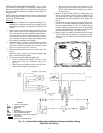
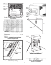
Pass the control wires through the hole provided in the cor-
ner post; then feed wires through the raceway built into the cor-
ner post to the 24-v barrier located on the left side of the control
box. See Fig. 10. The raceway provides the UL required clear-
ance between high- and low-voltage wiring.
HEAT ANTICIPATOR SETTINGS — Set heat anticipator set-
tings at .14 amp for first stage and .14 for second stage heating,
when available.
Step 8 — Adjust Factory-Installed Options
MOISTUREMISER DEHUMIDIFICATION PACKAGE —
MoistureMiser package operation can be controlled by field
installation of a Carrier-approved humidistat (Fig. 11). To
install the humidistat:
1. Route humidistat cable through hole provided in unit cor-
ner post.
2. Feed wires through the raceway built into the corner post
to the 24-v barrier located on the left side of the control
box. See Fig. 10. The raceway provides the UL-required
clearance between high- and low-voltage wiring.
3. Use a wire nut to connect humidistat cable into low-
voltage wiring as shown in Fig. 12.
APOLLO CONTROL — The optional Apollo control is used
to actively monitor all modes of operation as well as indoor
(evaporator) fan status, filter status, and indoor-air quality. The
Apollo control is designed to work with Carrier TEMP and
VVT
®
systems.
The thermostat must be wired to the Apollo Control before
starting the unit. Refer to the Apollo Control installation
instructions for information on installing the thermostat.
DISCONNECT SWITCH — The optional disconnect switch
is non-fused. The switch has the capability of being locked in
place for safety purposes.
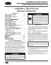
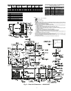
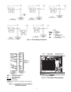
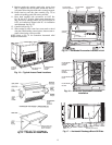
Fig. 7 — Gas Piping Guide (With Accessory
Thru-the-Curb Service Connections)
LEGEND
*Field supplied.
NOTE: Follow all local codes.
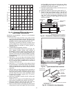
SPACING OF SUPPORTS
NFGC —
National Fuel Gas Code
STEEL PIPE
NOMINAL DIAMETER
(in.)
SPACING OF SUPPORTS
X DIMENSION
(ft)
1
/
2
3
/
4
or 1
1
1
/
4
or larger
6
8
10
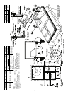
Fig. 6 — Flue Hood Details