


31
HEATING, UNITS WITHOUT ECONOMIZER — When
the thermostat calls for heating, terminal W1 is energized. The
induced-draft motor is energized and the burner ignition se-
quence begins. The indoor (evaporator) fan motor (IFM) is en-
ergized 45 seconds after a flame is ignited. When additional
heat is needed, W2 is energized and the high-fire solenoid on
the main gas valve (MGV) is energized. When the thermostat
is satisfied and W1 is deenergized, the IFM stops after a
45-second time-off delay.
COOLING, UNITS WITH DURABLADE ECONO-
MIZER — When the outdoor-air temperature is above the out-
door-air thermostat (OAT) setting and the room thermostat
calls for cooling, compressor contactor is energized to start
compressor and the outdoor (condenser) fan motor (OFM).
The indoor (evaporator) fan motor (IFM) is energized and the
economizer damper moves to the minimum position. After the
thermostat is satisfied, there is a 30-second delay before the
evaporator fan turns off. The damper then moves to the fully-
closed position. When using continuous fan, the damper moves
to the minimum position.
When the outdoor-air temperature is below the OAT setting
and the thermostat calls for cooling, the economizer damper
move to the minimum position. If the supply-air temperature is
above 57 F, the damper continues to open until it reaches the
fully-open position or until the supply-air temperature drops
below 52 F.
When the supply-air temperature falls between 57 F and
52 F, the damper will remain at an intermediate open position.
If the supply-air temperature falls below 52 F, the damper will
modulate closed until it reaches the minimum position or until
the supply-air temperature is above 52 F. When the thermostat
is satisfied, the damper moves to the fully closed position when
using AUTO. fan or to the minimum position when using con-
tinuous fan.
If the outdoor air alone cannot satisfy the cooling require-
ments of the conditioned space, economizer cooling is integrat-
ed with mechanical cooling, providing two stages of cooling.
Compressor and the condenser fan will be energized and the
position of the economizer damper will be determined by the
supply-air temperature. When the second stage of cooling is
satisfied, the compressor and OFM will be deenergized. The
damper position will be determined by the supply-air tempera-
ture. When the first stage of cooling is satisfied, there is a
30-second delay before the evaporator fan shuts off. The damp-
er then moves to the fully closed position. When using a con-
tinuous fan, the damper moves to the minimum position.
COOLING, UNITS WITH ECONOMI$ER — When the
Outdoor Air Temperature (OAT) is above the ECON SP set
point and the room thermostat calls for Stage 1 cooling (R to
G +Y1), the indoor-fan motor (IFM) is energized and the
EconoMi$er damper modulates to minimum position. The
compressor contactor is energized starting the compressor and
outdoor-fan motor (OFM). After the thermostat is satisfied, the
damper modulates to the fully closed position when the IFM is
deenergized.
When the OAT is below the ECON SP set point and the
room thermostat calls for Stage 1 cooling (R to G + Y1), the
EconoMi$er modulates to the minimum position when the
IFM is energized. The EconoMi$er provides Stage 1 of cooling
by modulating the return and outdoor air dampers to maintain a
55 F supply air set point. If the supply-air temperature (SAT) is
greater than 57 F, the EconoMi$er modulates open, allowing a
greater amount of outdoor air to enter the unit. If the SAT drops
below 53 F, the outdoor-air damper modules closed to reduce
the amount of outdoor air. When the SAT is between 53 and
57 F, the EconoMi$er maintains its position.
HEATING, UNITS WITH ECONOMIZER — When the ther-
mostat calls for heating, terminal W1 is energized. The
induced-draft motor is energized and the burner ignition se-
quence begins. The indoor (evaporator) fan motor (IFM) is en-
ergized 45 seconds after a flame is ignited and the damper
moves to the minimum position. When additional heat is need-
ed, W2 energized and the high-fire solenoid on the main gas
valve (MGV) is energized. When the thermostat is satisfied
and W1 is deenergized, the IFM stops after a 45-second time-
off delay. The economizer damper then moves to the fully
closed position. When using continuous fan, the damper will
remain in the minimum position.
UNITS WITH MOISTUREMISER DEHUMIDIFICATION
PACKAGE — When thermostat calls for cooling, terminals G
and Y1 and the compressor contactor C1 is energized. The in-
door (evaporator) fan motor (IFM), compressor, and outdoor
(condenser) fan motor (OFM) start. The OFM runs continuous-
ly while the unit is in cooling. As shipped from the factory,
MoistureMiser dehumidification circuit is always energized. If
MoistureMiser circuit modulation is desired, a field-installed,
wall-mounted humidistat is required.
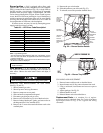
If the MoistureMiser humidistat is installed and calls for the
MoistureMiser subcooler coil to operate, the humidistat inter-
nal switch closes. This energizes and closes the liquid line sole-
noid valve coil (LLSV) of the MoistureMiser circuit, forcing
the hot liquid refrigerant of the liquid line to enter the subcooler
coil (see Fig. 39). As the hot liquid passes through the subcool-
er coil, it is exposed to the cold supply airflow coming off from
the evaporator coil and the liquid is further cooled to a temper-
ature approaching the evaporator coil leaving-air temperature.
The state of the refrigerant leaving the subcooler coil is a high-
ly subcooled liquid refrigerant. The liquid then enters a thermo-
static expansion valve (TXV) where the liquid is dropped to a
lower pressure. The TXV does not have a pressure drop great
enough to change the liquid to a 2-phase fluid. The TXV can
throttle the pressure drop of the liquid refrigerant and maintain
proper conditions at the compressor suction valve over a wide
range of operating conditions. The liquid then enters a second
fixed restrictor expansion device for a second pressure drop to
a 2-phase fluid. The liquid proceeds to the evaporator coil at a
temperature lower than normal cooling operation. This lower
temperature is what increases the latent capacity of the rooftop.
The 2-phase refrigerant passes through the evaporator and is
changed into a vapor. The air passing over the evaporator coil
will become colder than during normal operation as a result of
the colder refrigerant temperatures. However, as it passes over
the subcooler coil, the air will be warmed slightly.
As the refrigerant leaves the evaporator, the refrigerant
passes a low-pressure switch in the suction line. This low-
pressure switch will de-activate the MoistureMiser package
when the suction pressure reaches 60 psig. The low-pressure
switch is an added safety device to protect against evaporator
coil freeze-up. The low-pressure switch will only de-activate
and open the liquid line solenoid valve in the MoistureMiser
circuit. The compressors will continue to run as long as there is
a call for cooling, regardless of the position of the low-pressure
switch. The solenoid valve and the MoistureMiser package will
be re-activated only when the call for cooling has been satis-
fied, the low-pressure switch has closed, and a new call for
cooling exists. The crankcase heaters on the scroll compressor
provide additional protection for the compressor due to the ad-
ditional refrigerant charge in the subcooler.
When the humidistat is satisfied, the humidistat internal
switch opens cutting power to and opening the LLSV. The re-
frigerant is routed back through the evaporator and the sub-
cooler coil is removed from the refrigerant loop.
When the thermostat is satisfied, C1 is deenergized and the
compressor and OFM shut off. After a 30-second delay, the
IFM shuts off. If the thermostat fan selector switch is in the ON
position, the IFM will run continuously.