


4
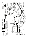
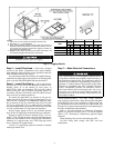
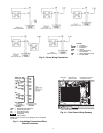
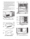
Step 5 — Install Flue Hood —
Flue hood is shipped
screwed to the burner compartment access panel. Remove
from shipping location and, using screws provided, install flue
hood in location shown in Fig. 5 and 6.
For units being installed in California Air Quality Manage-
ment Districts which require NO
x
emissions of 40 nanograms/
joule or less, kit CRLOWNOX001A00 must be installed.
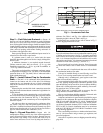
Step 6 — Install Gas Piping —
Unit is equipped for
use with type of gas shown on nameplate. Refer to local
building codes, or in the absence of local codes, to
ANSI Z223.1-1984 and addendum Z223.1A-1987 entitled
National Fuel Gas Code. In Canada, installation must be in
accordance with the CAN1.B149.1 and CAN1.B149.2 instal-
lation codes for gas burning appliances.
For natural gas applications, gas pressure at unit gas con-
nection must not be less than 4 in. wg or greater than 13 in. wg
while the unit is operating. On 48HJ005-007 high-heat units,
the gas pressure at unit gas connection must not be less than
5 in. wg or greater than 13 in. wg while the unit is operating.
For propane applications, the gas pressure must not be less than
5 in. wg or greater than 13 in. wg at the unit connection.
Size gas supply piping for 0.5 in. wg maximum pressure
drop. Do not use supply pipe smaller than unit gas connection.
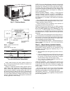
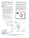
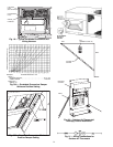
Support gas piping as shown in the table in Fig. 7. For ex-
ample, a
3
/
4
-in. gas pipe must have one field-fabricated support
beam every 8 ft. Therefore, an 18-ft long gas pipe would have a
minimum of 3 support beams, and a 48-ft long pipe would
have a minimum of 6 support beams.
See Fig. 7 for typical pipe guide and locations of external
manual gas shutoff valve.
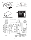
Step 7 — Make Electrical Connections
FIELD POWER SUPPLY — All units except 208/230-v
units are factory wired for the voltage shown on the nameplate.
If the 208/230-v unit is to be connected to a 208-v power sup-
ply, the transformer
must
be rewired by moving the black wire
from the 230-v terminal on the transformer and connecting it to
the 200-v terminal from the transformer.
Refer to unit label diagram for additional information.
Pigtails are provided for field service. Use factory-supplied
splices or UL (Underwriters’ Laboratories) approved copper
connector.
When installing units, provide a disconnect per NEC.
All field wiring must comply with NEC and local
requirements.
Unit cabinet must have an uninterrupted, unbroken electri-
cal ground to minimize the possibility of personal injury if
an electrical fault should occur. This ground may consist of
electrical wire connected to unit ground lug in control com-
partment, or conduit approved for electrical ground when
installed in accordance with NEC (National Electrical
Code), ANSI/NFPA (National Fire Protection Associa-
tion), latest edition, and local electrical codes.
Do not use
gas piping as an electrical ground.
Failure to follow this
warning could result in the installer being liable for per-
sonal injury of others.
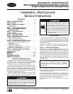
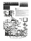
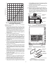
NOTES:
1. Place unit on curb as close as possible to the duct end.
2. Dimension in ( ) is in millimeters.
3. Hook rigging shackles through holes in base rail as shown in
detail ‘‘A.’’ Holes in base rails are centered around the unit cen-
ter of gravity. Use wooden top skid when rigging to prevent rig-
ging straps from damaging unit.
4. Weights include base unit without economizer. See Table 1 for
unit operating weights with accessory economizer.
All panels must be in place when rigging.
Fig. 4 — Rigging Details
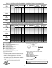
UNIT
48HJ
MAX
WEIGHT
“A” “B” “C”
lb kg in. mm in. mm in. mm
004
530 240 73.69 1872 35.50 902 33.31 847
005
540 245 73.69 1872 35.50 902 33.31 847
006
560 254 73.69 1872 35.50 902 33.31 847
007
615 279 73.69 1872 35.50 902 33.31 847