


3
Step 2 — Field Fabricate Ductwork —
Secure all
ducts to roof curb and building structure on vertical discharge
units.
Do not connect ductwork to unit.
For horizontal applica-
tions, field-supplied isolation flanges should be attached to hor-
izontal discharge openings and all ductwork should be secured
to the flanges. Insulate and weatherproof all external ductwork,
joints, and roof openings with counter flashing and mastic in
accordance with applicable codes.
Ducts passing through an unconditioned space must be in-
sulated and covered with a vapor barrier.
If a plenum return is used on a vertical unit, the return
should be ducted through the roof deck to comply with applica-
ble fire codes.
A minimum clearance is not required around ductwork.
Cabinet return-air static shall not exceed –.35 in. wg with
Durablade economizer, or –.30 in. wg with EconoMi$er, or
–.45 in. wg without economizer.
These units are designed for a minimum continuous return-
air temperature in heating of 50 F (dry bulb), or an intermittent
operation down to 45 F (dry bulb), such as when used with a
night setback thermostat.
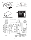
Step 3 — Install External Trap for Condensate
Drain —
The unit’s
3
/
4
-in. condensate drain connections are
located on the bottom and side of the unit. Unit discharge
connections do not determine the use of drain connections;
either drain connection can be used with vertical or horizontal
applications.
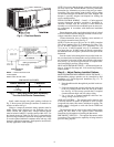
When using the standard side drain connection, ensure the
plug (Red) in the alternate bottom connection is tight before in-
stalling the unit.
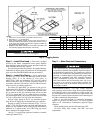
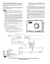
To use the bottom drain connection for a roof curb installa-
tion, relocate the factory-installed plug (Red) from the bottom
connection to the side connection. See Fig. 3. The piping for
the condensate drain and external trap can be completed after
the unit is in place.
All units must have an external trap for condensate drain-
age. Install a trap 4-in. deep and protect against freeze-up. If
drain line is installed downstream from the external trap, pitch
the line away from the unit at 1 in. per 10 ft of run. Do not use a
pipe size smaller than the unit connection (
3
/
4
in.).
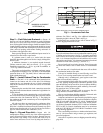
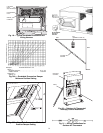
Step 4 — Rig and Place Unit —
Inspect unit for
transportation damage, and file any claim with transportation
agency. Keep unit upright and do not drop. Spreader bars are
not required if top crating is left on unit, and rollers may be
used to move unit across a roof. Level by using unit frame as a
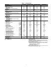
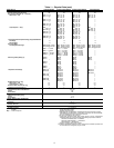
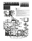
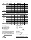
reference. See Table 1 and Fig. 4 for additional information.
Operating weight is shown in Table 1 and Fig. 4.
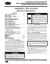
Lifting holes are provided in base rails as shown in Fig. 5.
Refer to rigging instructions on unit.
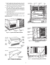
POSITIONING — Maintain clearance around and above unit
to provide minimum distance from combustible materials, prop-
er airflow, and service access. See Fig. 5. A properly positioned
unit will have the following clearances between unit and roof
curb;
1
/
4
-in. clearance between roof curb and base rails on each
side and duct end of unit;
1
/
4
in. clearance between roof curb and
condenser coil end of unit. (See Fig. 1, section C-C.)
Do not install unit in an indoor location. Do not locate unit
air inlets near exhaust vents or other sources of contaminated
air.
Be sure that unit is installed such that snow will not block
the combustion intake or flue outlet.
Unit may be installed directly on wood flooring or on Class
A, B, or C roof-covering material when roof curb is used.
Although unit is weatherproof, guard against water from
higher level runoff and overhangs.
Locate mechanical draft system flue assembly at least 48 in.
from any opening through which combustion products could
enter the building, and at least 48 in. from an adjacent building.
When unit is located adjacent to public walkways, flue assem-
bly must be at least 7 ft above grade.
NOTE: When unit is equipped with an accessory flue dis-
charge deflector, allowable clearance is 18 inches.
Flue gas can deteriorate building materials. Orient unit such
that flue gas will not affect building materials.
Adequate combustion-air space must be provided for proper
operation of this equipment. Be sure that installation complies
with all local codes and Section 5.3, Air for Combustion and
Ventilation, NFGC (National Fuel Gas Code), ANSI (Ameri-
can National Standards Institute) Z223.1-1984 and addendum
Z223.1a-1987. In Canada, installation must be in accordance
with the CAN1.B149.1 and CAN1.B149.2 installation codes
for gas burning appliances.
Flue vent discharge must have a minimum horizontal clear-
ance of 4 ft from electric and gas meters, gas regulators, and
gas relief equipment.
After unit is in position, remove shipping materials and rig-
ging skids.
All panels must be in place when rigging and lifting.
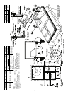
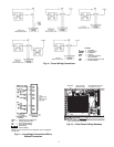
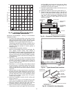
MAXIMUM ALLOWABLE
DIFFERENCE (in.)
A-B B-C A-C
0.5 1.0 1.0
Fig. 2 — Unit Leveling Tolerances
DRAIN PLUG
CONDENSATE PAN (SIDE VIEW)
NOTE: Drain plug is shown in factory-installed position.
Fig. 3 — Condensate Drain Pan