


35
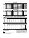
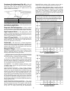
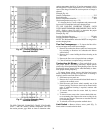
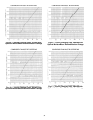
TO USE COOLING CHARGING CHART, STANDARD
UNIT — Take the outdoor ambient temperature and read
the suction pressure gage. Refer to charts to determine what
suction temperature should be. If suction temperature is high,
add refrigerant. If suction temperature is low, carefully recover
some of the charge. Recheck the suction pressure as charge is
adjusted.
Example (Fig. 46):
Outdoor Temperature. . . . . . . . . . . . . . . . . . . . . . . . . . . . . . .75 F
Suction Pressure. . . . . . . . . . . . . . . . . . . . . . . . . . . . . . . . 70 psig
Suction Temperature should be. . . . . . . . . . . . . . . . . . . . . . .48 F
(Suction temperature may very ± 5 F.)
If a charging device is used, temperature and pressure read-
ings must be accomplished using the charging charts.
TO USE COOLING CHARGING CHARTS, UNITS
WITH MOISTUREMISER DEHUMIDIFICTION PACK-
AGE — Refer to charts (Fig. 48-51) to determine the proper
leaving condenser pressure and temperature.
Example (Fig. 48):
Leaving Condenser Pressure. . . . . . . . . . . . . . . . . . . . . 250 psig
Leaving Condenser Temperature . . . . . . . . . . . . . . . . . . . 105 F
NOTE: The MoistureMiser subcooler MUST be energized to
use the charging charts.
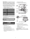
Flue Gas Passageways —
To inspect the flue collec-
tor box and upper areas of the heat exchanger:
1. Remove the combustion blower wheel and motor assem-
bly according to directions in Combustion-Air Blower
section below.
2. Remove the 3 screws holding the blower housing to the
flue cover.
3. Remove the flue cover to inspect the heat exchanger.
4. Clean all surfaces as required using a wire brush.
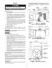
Combustion-Air Blower —
Clean periodically to en-
sure proper airflow and heating efficiency. Inspect blower
wheel every fall and periodically during heating season. For the
first heating season, inspect blower wheel bimonthly to deter-
mine proper cleaning frequency.
To inspect blower wheel, remove draft hood and screen.
Shine a flashlight into opening to inspect wheel. If cleaning is
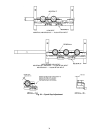
required, remove motor and wheel as follows:
1. Slide burner access panel out.
2. Remove the 5 screws that attach induced-draft motor as-
sembly to the vestibule cover.
3. Slide the motor and blower wheel assembly out of the
blower housing. The blower wheel can be cleaned at this
point. If additional cleaning is required, continue with
Steps 4 and 5.
4. To remove blower from the motor shaft, by remove
2 setscrews.
5. To remove motor, remove the 4 screws that hold the mo-
tor to mounting plate. Remove the motor cooling fan by
removing one setscrew. Then remove nuts that hold mo-
tor to mounting plate.
6. To reinstall, reverse the procedure outlined above.
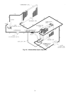
Limit Switch —
Remove blower access panel (Fig. 5).
Limit switch is located on the fan deck.
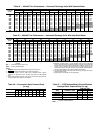
Fig. 47 — Cooling Charging Chart,
Standard 48HJ007
Fig. 46 — Cooling Charging Chart,
Standard 48HJ006