


39
TROUBLESHOOTING
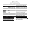
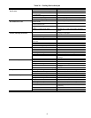
Refer to Tables 30-36 for troubleshooting details.
Table 30 — LED Error Code Service Analysis
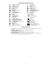
LEGEND
SYMPTOM CAUSE REMEDY
Hardware failure.
(LED OFF)
Loss of power to control module (IGC). Check 5 amp fuse on IGC, power to unit, 24-v circuit breaker, and
transformer. Units without a 24-v circuit breaker have an internal
overload in the 24-v transformer. If the overload trips, allow
10 minutes for automatic reset.
Fan ON/OFF delay modified
(LED/FLASH)
High limit switch opens during heat
exchanger warm-up period before fan-on
delay expires.
Limit switch opens within three minutes
after blower-off delay timing in Heating mode.
Ensure unit is fired on rate and temperature rise is correct.
Ensure units’ external static pressure is within application guidelines.
Limit switch fault.
(LED 2 flashes)
High temperature limit switch is open. Check the operation of the indoor (evaporator) fan motor.
Ensure that the supply-air temperature rise is in accordance with
the range on the unit nameplate.
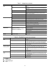
Flame sense fault.
(LED 3 flashes)
The IGC sensed flame that should not be
present.
Reset unit. If problem persists, replace control board.
4 consecutive limit
switch faults.
(LED 4 flashes)
Inadequate airflow to unit. Check operation of indoor (evaporator) fan motor and that supply-air
temperature rise agrees with range on unit nameplate information.
Ignition lockout.
(LED 5 flashes)
Unit unsuccessfully attempted ignition for
15 minutes.
Check ignitor and flame sensor electrode spacing, gaps, etc.
Ensure that flame sense and ignition wires are properly
terminated. Verify that unit is obtaining proper amount of gas.
Induced-draft motor fault.
(LED 6 flashes)
IGC does not sense that induced-draft
motor is operating.
Check for proper voltage. If motor is operating, check the
speed sensor plug/IGC Terminal J2 connection. Proper
connection: PIN 1— White, PIN 2 — Red, PIN 3 — Black.
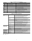
Rollout switch fault.
(LED 7 flashes)
Rollout switch has opened. Rollout switch will automatically reset, but IGC will continue to
lock out unit. Check gas valve operation. Ensure that induced-
draft blower wheel is properly secured to motor shaft.
Reset unit at unit disconnect.
Internal control fault.
(LED 8 flashes)
Microprocessor has sensed an error in the
software or hardware.
If error code is not cleared by resetting unit power, replace the IGC.
If the IGC must be replaced, be sure to ground yourself to dissi-
pate any electrical charge that may be present before handling
new control board. The IGC is sensitive to static electricity and
may be damaged if the necessary precautions are not taken.
IMPORTANT: Refer to heating troubleshooting for additional
heating section troubleshooting information.
IGC —
Integrated Gas Unit Controller
LED —
Light-Emitting Diode